
Accessory List

TP-8101, TP-8102, TP-8121, TP-8124
F-27382-1 © Copyright 2006 TAC. All Rights Reserved. 271
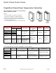
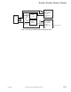
Figure 3 Options for Quantities of 24 or More of Each Part Number.
Specifications
Accessories
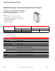
Construction Self-contained room controller with a 1000 Ω Balco sensing element with single or dual output(s).
Ambient temperature limits
Shipping and storage: -40 to 160°F (-40 to 71°C).
Operating: 40 to 140°F (4.4 to 60°C).
Connections
Coded screw terminals. T-8101 and TP-8102 have 6 in. color coded pigtails in addition to coded
screw terminals.
Cover Beige colored plastic.
Locations NEMA Type 1.
Mounting Panel assembly order AD-8953 mounting track separately.
Dimensions 4-3/8 H x 2-3/4 W x 1-5/8 D in. (111 x 70 x 41 mm).
General Instructions Refer to F-18097. TP-8121, 8124: Refer to F-22615.
Model No. Description
AT-504 Plaster hole cover kit (small).
AT-505 Surface mounting base.
AT-546 Auxiliary mounting plate.
AT-1103 Wire guard.
AT-1104 Cast aluminum guard.
AT-1155 Plastic guard.
AT-1165 Plastic guard.
TP-810x only
AD-8122 Signal adaptor for dual outputs (two direct acting).
AD-8123 Signal adaptor for dual outputs (one direct, one reverse acting).
AD-8124 Signal adaptor for dual outputs (one reverse, one direct acting).
AD-8953 Mounting track.
AD-8969-201 Offset resistor kit; 5, 10, 15 and 20°F.
AD-8969-901 Extended throttling range jumper.
AT-61 Series Brushed bronze cover plates.
AT-101 Lock cover kit.
AT-104 Dial stop pins.
AT-602 Selector switch sub-base DP4T.
AT-603 Selector switch sub-base DP4T, one DPDT.
AT-8122 Remote setpoint adjuster, dual scale 20 to 120°F (-6 to 49°C).
AT-8155 Remote setpoint adjuster, dual scale 50 to 250°F (10 to 121°C).
AT-8158 Remote setpoint adjuster, dual scale 55 to 85°F (13 to 29°C).
TS-8131 Room button type sensor.
TS-8201 Duct/immersion sensor.
TS-8261 Light fixture sensor.
TS-8405 5 ft. (1.5 m) averaging sensor.
TS-8422 22 ft. (6.7 m) averaging sensor.
TS-8601 Selective ratio discharge sensor.
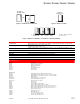
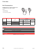
with
insert insert
TP-810x††
TP-810x-116††
TP-812x††
TP-812x-116††
Blank Cover Onl
y
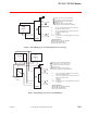
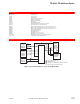
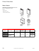
Figure 1 Standard Cover with Inserts.
Figure 2 Blank Cover Only.
F
C
††5/64 in. Allen screw used
to secure cover.
TP-810x-399
TP-810x-398
-400
-410
-403††
-413††
-404††
-414††