
Accessory List
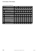


TA-168 Series
238
© Copyright 2006 TAC. All Rights Reserved. F-27382-1
Typical Applications
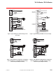
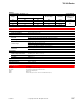
Figure 1 Typical Wiring for Proportional Control.
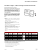
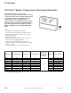
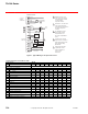
T168 Therminal Function and Model Table.
Model Number TA-168
-1 -2 -3 -4 -5 -6 -7 -8 -9
Terminal Function
Line Voltage Fan Terminals
1L1Fan Hot —XX———XX—
2L2Lo Fan — X X ——————
3L2Med Fan — X X ——————
4 L2 Hi or Single Speed Fan — X X — — — X X —
Low Voltage Terminals
524 Vac input XXXXXXXXX
624 Vac input XXXXXXXXX
7Setback XXXXXXXXX
10Main Output Signal XXXXXXXXX
11 Secondary Output Signal X X — — — X — X —
12Demand Output 24 Vac —XX—XXXX—
13Auxiliary or Staged Heat 24 Vac XXXXXXXXX
14 Damper Output 24 Vac — X X — — — X X —
15Remote Temperature Sensor Optional XXXXXXXXX
16Common Optional Sensors XXXXXXXXX
17Changeover Sensor Optional XXXXXXXXX
1
1
2
3
L1 (Hot)
LO
MED
HI FAN OR
SINGLE SPEED
L2 OR NEUTRAL
24 - 277 VAC
VOLTAGE
CONNECTION
3 SPEED FAN CONTROL
FAN
1
2
3
4
For demand fan control,
power a 24V fan relay
using Terminal 12 as
the output. Output limited
10 VA.
Can be used for second
stage 24 Vac heat output or
single stage 24 Vac electric
heat output by setting
dipswitch #2.
LOW VOLTAGE
CONNECTIONS
24 VAC
XFMR
SETBACK INPUT
SETBACK
SWITCH
SECONDARY
0-10 VDC
OUTPUT
MAIN
0-10 VDC
OUTPUT
5
6
7
10
11
12
13
OPTIONAL REMOTE TEMP SENSOR
OPTIONAL CHANGEOVER,
PIPE/AIR SENSOR
15
16
17
FAN
OUTPUT
24 VAC 1
24 VAC 2
4
14
AUXILIARY OR
STAGED OUTPUT
DAMPER
OUTPUT
3
2
2
5
Teminals 10 and 11 are
connected to the actuators
respective inputs, terminal
6 to the actuators
respective common.
Terminals 12, 13, and 14 are
connected to the devices
respective input, terminal 5 to
the devices respective
common.
4
5
Setback must be with a
separate dry contact
between terminals 5
and 7 of each
thermostat.