
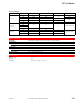
Accessory List

PP-8311 Series
208
© Copyright 2006 TAC. All Rights Reserved. F-27382-1
Accessories
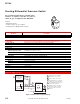
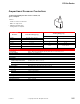
Typical Applications
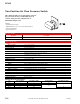
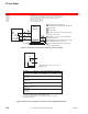
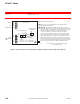
Figure 1 PP-8311 Series Pressure Transducer Terminal Designations Shown with Cover Removed.
Model No. Description
TOOL-95-1 Pneumatic calibration tool kit.
L2
24G
L1
24H
GND
–
1-5
Vdc
+
–
4-20
mA
+
P3
P2
P1
Cover removed
Jumper
P1 to P2 — 3 to 15 psig input
P2 to P3 — 0 to 20 psig input
GAIN
CAL
Cover Mounting Post
GAIN (Span)
Adjustment
CAL (Start Point)
Adjustment
3 to 15 psig (21 to 103 kPa) Input Air Signal
(0 to 20 psig optional).
Neutral
Hot
E
arth Ground
Output
Signals
Supply Voltage (see Model Chart)
2
1
1 When using 0 to 20 psig input (P2 to P3), GAIN and CAL
adjustments must be made.
2 CAUTION: The outputs for voltage and current do not have a
common negative electrical reference. This means devices used
with the PP-8311, when using both output capabilities, cannot be
connected to devices which have a common (-) negative
connection. Outputs 1 to 5 Vdc & 4 to 20 mA must not be
connected to any external voltage sources and should only be
connected to other devices or loads which are purely resistive.
When multiple PP-8311-024 units are powered from the same
transformer, damage will result unless all 24G power leads are
connected to the same power lead on all devices. It is mandatory
that correct phasing be maintained when powering more than one
device from a single transformer. Refer to EN206 F-26363.