
Accessory List


AE-600 Series
10
© Copyright 2006 TAC. All Rights Reserved. F-27382-1
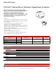
Control Cabinets
Model Chart
Specifications
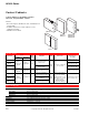
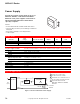
Control cabinets for mounting of electric,
electronic, and pneumatic controls.
Features:
• New lock design for AE-629, 630, 631, and 632 improves
locking ability.
• Available subpanels for certain cabinets for easy
equipment mounting.
• AE-662 Series UL listed.
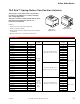
Model No.
Door
Steel
Gauge
Subpanel Finish Knockouts
Dimensions
in. (mm)
Type Opening
AE-629
Single,
continuously
hinged
Right or
left-handed
18
AE-630-101
16 GA perforated
14-1/2 x 20 in.
Beige
paint
For 3/4 in. conduit, two
on each side
24 W x 16 H x 7 D
(610 x 406 x 178)
AE-630
16 W x 24 H x 7 D
(406 x 610 x 178)
AE-631
AE-631-101
22-1/2 x 28 in.
24 W x 32 H x 7 D
(610 x 813 x 178)
AE-632
Double,
continuously
hinged
Right and
left-handed
16
Obtain locally, one or two
subpanels may be used
42 W x 36 H x 7 D
(1067 x 914 x 178)
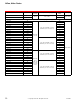
AE-662-501
Single,
three hinges
Left-handed 14
16 gage, perforated for
#8 Type A sheet metal
screws, flanged, included
White
paint
Five on top & bottom,
six on each side for 3/4
in. or 1 in. conduit.
Eight 3/8 in. dia. on top
& bottom, ten on each
side for 3/8 in.
bulkhead barbed
pneumatic fittings
24 W x 30 H x 7-1/2 D
(610 x 762 x 191)
AE-662-502
16 gage, solid, flanged,
included
AE-662-503
None, mounting studs for
subpanel not provided
Construction
Doors
Locking type, supplied with keys, rigidly supported. The doors are easily removed for protection on
job site installation or mounting of components. Refer to Model Chart.
Steel gauge Refer to Model Chart.
Knockouts Aligned so that a short nipple may be used to couple the panels. Refer to Model Chart.
Appearance Refer to Model Chart.
Locations NEMA Type 1.
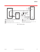
Mounting Four extruded mounting holes 1/4 in. (6 mm).
Dimensions Refer to Model Chart.
Agency Listing AE-662-xxx — UL Listed.
General Instructions Refer to F-15609.
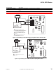
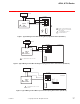
AE-600
Series
AE-629
AE-662-501
AE-662-502
AE-662-503
AE-630
AE-631
AE-632