
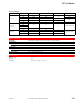
Accessory List

PF-126
202
© Copyright 2006 TAC. All Rights Reserved. F-27382-1
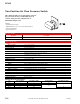
Floating Differential Pressure Switch
Model Chart
Specifications
Typical Applications
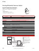
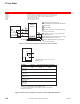
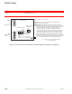
Figure 1 Switch Action and Typical Wiring.
For use with reversible electric actuated valves,
actuators, or sequence controllers for control of
steam, air, gas, or liquid pressure differential.
Features:
• Adjustable setpoint.
• Usable on steam, air, gas, or liquid.
• Floating action for MP-gear train actuators.
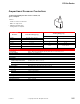
Model No. Description
PF-126 Refer to Specifications.
Control range 8 to 60 psi (57 to 414 kPa). Graduated scale and external adjustment screw.
Sensing elements High and low pressure bellows with opposing spring mechanism.
Differential 2 psi (14 kPa) fixed.
Maximum static pressure 180 psi (1241 kPa).
Environment
Ambient temperature limits
Shipping and storage: -40 to 140°F (-40 to 60°C).
Operating: 35 to 140°F (0 to 60°C).
Humidity 5 to 95% RH, non-condensing.
Locations NEMA Type 1.
Electrical switch Floating SPDT. Arc suppressor included with unit.
Ratings 1.0 amps at 24 Vac, 60 Hz.
Connections
Electrical Coded screw terminals.
Pressure connectors Two 1/4 in. male flare.
Case All metal with 1/2 in. conduit opening.
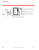
Mounting In any position.
Dimensions 7-7/8 H x 4 W x 2 D in. (200 x 102 x 51 mm).
General Instructions Refer to F-11384.
PF
-
126
MP-3xx, 4xx,
4xxx,
97xx
CYZR-818-3
Arc Suppressor
Packaged with
PF-126
Differential
Pressure Switch
G
H
Blue
AC Supply
Decrease
in
Differential
5
5
4
3
22 7
1
6
Red
White
3
2
X
B
R
C
1 Install under cover of actuator.
2 Rotates CW or closes valve.
3 Rotates CCW or opens valve.
4 Determine direction of rotation by
looking at end of actuator shaft.
5 These terminals marked L1 & L2
on line voltage actuators.
6 Terminals 1,5 & 6 are used for
built-in aux. switch (if present).
7 R contact makes on pressure
decrease.