
Accessory List
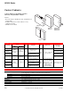


AE-504
F-27382-1 © Copyright 2006 TAC. All Rights Reserved. 9
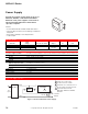
Typical Applications
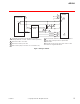
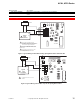
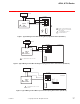
Figure 1 Wiring for AE-504.
2
3
6
7 7
7
4
4
5
5
1
H
AE-504
Paralleling
Relay
Transmitting
Potentiometer
4
X
2
3
7
G
Follow-Up
Actuator
8
Red/Black
Yellow/Black
Brown/Yellow
Brown
Black
Blue/Black
cw
680 Ω680 Ω
50 Ω
Ω
Ω
1 Transmitting potentiometer typically AM-332 on actuator,
manual potentimeter, or 135 slidewire controller (1.5W min.).
2 Shaft rotates CW or closes valve.
3 Shaft rotates CCW or opens valve.
4 Make resistor & jumper connections on 24 V actuators only.
Ω
5 These terminals marked L1, L2 on line voltage actuators.
6 Line voltage follow-up actuators require built-in
transformers.
7 Two 680 0.5 W resistors and a 50 resistor for 24 V
actuator are supplied with AE-504.
ccw