
Accessory List
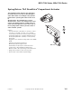


MU-12313
F-27382-1 © Copyright 2006 TAC. All Rights Reserved. 197
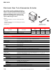
Accessories
Typical Applications
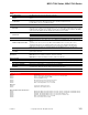
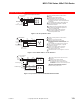
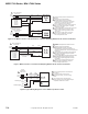
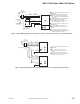
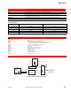
Figure 1 Typical Wiring for MU-12313.
Specifications (Continued)
Case Glass reinforced thermoplastic (PET) cover, plated steel case.
Mounting Any position. Five 9/32 in. (7.1 mm) mounting holes provided.
Crank arm for actuator
AM-112 included with actuator. 3/8 in. (9.5 mm) slot provides for adjustable radius from
7/8 in. (22 mm) to 3-1/8 in. (79 mm).
Dimensions 5-1/2 H x 5 W x 7-9/32 D in. (140 x 127 x 185 mm). 3/8 in. (9.5 mm) shaft diameter.
General Instructions Refer to F-22174.
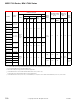
Throttling Ranges
a
a
Number of degrees change required at the sensor in order to produce the maximum rotation of the actuator output shaft.
Degree Rotation
T.R. as Factory Supplied F°(C°) T.R. with Jumper J1 Removed F° (C°)
75 7 (3.8) 3.5 (1.9)
90 8 (4.4) 4 (2.2)
110 10 (5.5) 5 (2.8)
160 14 (7.2) 7 (3.8)
180 16 (8.9) 8 (4.4)
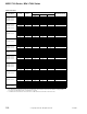
Model No. Description
Damper Linkage Accessories
AD-931-105 Min positioner.
AM-111 Crank arm for 5/16 in. diameter damper shaft.
AM-112 Crank arm for 3/8 in. diameter damper or MU-12313 actuator shaft.
AM-113 Crank arm for MU-12313 or 1/2 in. diameter damper shaft.
AM-115 Crank arm for 7/16 in. diameter damper shaft.
AM-122 Linkage connector straight type.
AM-123 Damper clip.
AM-125 5/16 in. diameter x 20 in. damper rod.
AM-125-048 5/16 in. diameter x 48 in. damper rod.
AM-132 Ball joint connector.
AM-219 Conduit cover kit.
AM-230 Crank arm for MU-12313-100.
AM-301 90° mounting bracket.
BDHE-55 Thermistor sensor.
Mixed or Discharge
Air Sensor
Occupied
Optional External
Minimum
Positioner
(AD-931-105)
W
R (Yellow/Black)
B Inc
1 Remove factory jumper
if External Minimum
Positioner and/or
Occupied/Unoccupied
Switch are used.
MU-12313
Unoccupied
T
T1
L2
Hot L1
TR
TR1
P1
P
24 Vac
Class 22
Transformer
(Blue)
1