
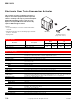
Accessory List
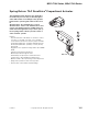


MS51-7103 Series, MSx1-7203 Series
F-27382-1 © Copyright 2006 TAC. All Rights Reserved. 195
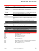
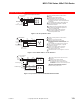
1 Provide overload protection and disconnect
as required.
2 With four actuators wired to one 500 ohm
resistor, a +2% shift of the control signal
may be required. (Actuator input impe
dance
is 80 k ohm.)
3 A field-supplied 500 ohm resistor (AM-708)
is required between the gray and
yellow/black leads to convert the 4 to 20
mAdc control signal to 2 to 10 Vdc.
4 Only connect common to
negative (-) leg of
control circuits.
5 To reverse actuator control function
(direct/reverse action), use the reversing
switch.
To Additional
Actuators
Grn/Yel
Hot (+DC)Red
Blk
Com
Com
Line
Volts
(-)
(+)
Control Signal
4 to 20 mA
Yel/Blk
Blu
(-)
(+)
Feedback Signal
2 to 10 Vdc
4
5
Gra
L R
AI
AO
MSx1-7203
3
1
500
24 Vac
Transformer
or 22- 30 Vdc
2
6
If the controller uses a full wave power
supply and does not provide isolated outputs,
a separate transformer is needed.
6
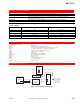
Figure 7 Typical Wiring Diagrams for Proportional Control 4 to 20 mA Converted to 2 to 10 Vdc Basic Models.
Red
Blk
Com
Hot (+DC)
Line
Volts
(-)
(+)
Yel/Blk
AI
Red
Blk
Com
Hot (+DC)
Yel/Blk
AI
Blu
AO
2
MSx1-7203-xxx
L R
MSx1-7203
L R
Com
Gra
Com
Gra
Grn/Yel
Grn/Yel
1
Control Signal
24 Vac
Transformer
or 22- 30 Vdc
2
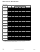
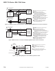
1 Provide overload protection and disconnect
as required.
2 To reverse actuator control function
(direct/reverse action), use the reversing
switch.
If the controller uses a full wave power
supply and does not provide isolated outputs,
a separate transformer is needed.
3
3
3
Figure 8 Typical Wiring Diagrams for Proportional Control 2 to 10 Vdc Models Wired in Parallel.