
Accessory List
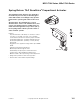


MS51-7103 Series, MSx1-7203 Series
194
© Copyright 2006 TAC. All Rights Reserved. F-27382-1
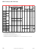
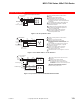
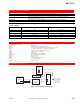
MS51-7103-x40
24 Vac Transformer
or 20-30 Vdc
Red (+20)
Line
V
olts
Blue (COM)
Yellow (OLP1)
Typical Controllers
CP-8102
TP-810X
TP-8121
TP-8124
TP-8232
TAC System 8000 controller
requiring external 20 Vdc
power from actuator
1
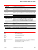
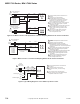
MS51-7103-x40
2
Red
Blk
Com
Hot (+DC)
24 Vac Transformer
or 20-30 Vdc
Line
V
olts
1
Red
Blk
Com
Hot (+DC)
Yel/Blk
Yel/Blk
White/Red
3
2 3
5
4 5
1 Provide overload protection and disconnect as
required.
2 Actuators may be wired in parallel.
All actuator black wires are connected to
the transformer's and controller's common and
all
red wires are connected to their hot lead.
Power consumption must be observed.
3 If the controller uses a full-wave power supply and
does not provide isolated outputs, a separate
transformer
is required.
4 If using multiple MS51-7103-040's with TAC System
8000 controller requiring 20 Vdc power; tape
off red +20 Vdc power supply leads on all but
one actuator.
5 Cable on some models contains more wires
than are used in applications. Only those
wires actually used are shown.
Figure 4 Two MS51-7103-x40 to TAC System 8000 Controllers Requiring External 20 Vdc Power from Actuator.
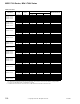
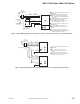
MS51-7103-x40
COM
OP1
Typical TAC System
8000 Controllers
CC-8111
CC-8118
CC-8218
CP-8161
CP-8261
24 Vac Transformer
or 20-30 Vdc
Line
Volts
1
Red
Blk
Com
Hot (+DC)
Yel/Blk
AI
2 3
Vdc
Feedback Signal
6 to 9 Vdc
(-)
(+)
AO
Violet
4 5
1 Provide overload protection and disconnect as
required.
2 Actuators may be wired in parallel
All actuator black wires are connected to
the transformers common and all red wires are
conn
ected to their hot lead. Power consumption must
be observed.
3 If the controller uses a full-wave power supply and
does not provide isolated outputs, a separate
transformer is required.
4 If using multiple MS51-7103-040's with TAC System
8000 controller requiring 20 Vdc power; tape
off red +20 Vdc power supply leads on all but
one actuator.
5 Cable on some models contains more wires
than are used in applications. Only those
wires actually used are shown.
Figure 5 MS51-7103-x40 to Controllers Not Requiring External 20 Vdc Power from Actuator.
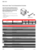
Feedback Signal
Red
Blk
Com
Hot (+DC)
Line
Volts
(-)
(+)
(-)
(+)
Control Signal
Yel/Blk
AI
Grn/Yel
Com
Gra
1
2
L R
MSx1-7203-xxx
BluAO
24 Vac
Transformer
or 22- 30 Vdc
1 Provide overload protection and disconnect
as required.
2
3
To reverse actuator control function
(direct/reverse action), use the reversing
switch.
If the controller uses a full wave power
supply and does not provide isolated outputs,
a separate transformer is needed.
3
Figure 6 Typical Wiring Diagram for 4 to 20 mAdc Proportional Control.