
Accessory List


MS41-634x Series
188
© Copyright 2006 TAC. All Rights Reserved. F-27382-1
Accessories
Typical Applications
Specifications (Continued)
Environment
Temperature limits
Shipping and Storage: -40 to 160°F (-40 to 71°C) ambient.
Operating: -25 to 140°F (-32 to 60°C).
Humidity 5 to 95% RH, non-condensing.
Locations NEMA 1, NEMA 4 (IEC IP56) with customer supplied water tight connectors.
Dimensions 10-27/32 H x 4 W x 4 D in. (275 x 102 x 102 mm).
Agency Listings
UL
UL-873, Underwriters Laboratories Listed (File #E9429 category: Temperature-Indicating and
Regulating Equipment.)
European Community EMC Directive (89/336/EEC). Low Voltage Directive (72/23/EEC).
CSA Canadian Standards C22.2 No. 24-93.
Australia
This product meets requirements to bear the C-Tick mark according to the terms specified by the
Communications Authority under the Radio Communications Act 1992.
General Instructions Refer to F-26745.
Model No. Description
AM-676 Universal shaft extension, approximately 9-1/2 in. long (242 mm) for use on 3/8 to 11/16 in. (10 to 17 mm) round shafts, 3/8 to
9/16 in. square shafts. (AM-753 clamps required).
AM-703 Span adjustment module mA/Vdc input to 2 to 10 Vdc output.
AM-704 Modulating interface pulse to 2 to 10 Vdc control.
AM-705 Positioner for 0 to 10 Vdc control.
AM-706 Positioner for 0 to 10 Vdc control.
AM-751 Standard anti-rotation bracket 9 in. long x 13/16 in. wide (229 x 21 mm), included with actuator.
AM-752 Optional anti-rotation bracket 4 in. long x 1-11/16 in. wide (102 x 43 mm), for narrow spaces.
AM-753 Damper shaft mounting clamps for 5/8 in. square shaft, 3/4 in. and 1 in. round shafts (two per package).
AM-754 Standard universal mounting clamps for 3/8 in. to 1/2in. (10 to 13 mm) round and square shafts, two included with actuator.
AM-755 Manual override crank.
AM-756 Metric conduit adaptor M20 x 1.5 to 1/2 in. NPT (two per package).
AV-609 5 and 6 in. Vx-9xxx valve linkage or 6 in VX-8000.
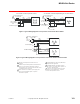
MS41-6343
Black
Black/Blue
24H
24G
24 Vac
GRDGreen/Yellow
White
Red
Black
+ IN
COM
+
-
Unused
(wire nut)
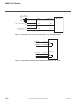
2 to 10 Vdc
Controller
500Ω
2
1 Unused conduit port must remain plugged with
a water tight pipe plug as shipped from factory
to maintain NEMA Type 4 or IP56 rating.
2 Ground wire may be Green on some models.
1
Power Wire Identification
Voltage Designation Wire Color
24 L1 Black
L2 Black/Blue
120 L1 Black
L2 White
240 L1 Brown
L2 Light Blue
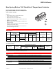
Figure 1 Typical Wiring Diagram for 2 to 10 Vdc Controller with a 24 Vac Actuator
(See Power Wiring Identification for 120 or 240 V Power).
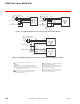
MS41-6343
Black
Black/Blue
24H
24G
24 Vac
GRDGreen/Yellow
4 to 20 mA
White
Red
Black
+IN
COM
+
-
500Ω
2
1 Unused conduit port must remain
plugged with a water tight pipe plug as
shipped from factory to maintain NEMA
Type 4 or IP56 rating.
2 Ground wire may be Green on some
models.
1
Power Wire Identification
Voltage Designation Wire Color
24 L1 Black
L2 Black/Blue
120 L1 Black
L2 White
240 L1 Brown
L2 Light Blue
Figure 2 Typical Wiring Diagram for 4 to 20 mA Controller with a 24 Vac Actuator
(See Power Wiring Identification for 120 or 240 V Power).