
Accessory List
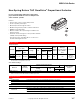


MS4D-7033 Series, MS4D-8033
186
© Copyright 2006 TAC. All Rights Reserved. F-27382-1
Typical Applications
2
3
2
3
5
6
1
1
6
MS4D-xxx3-xx0
24 Vac Transformer
or 20-30 Vdc
Line
Volts
Vdc Control Signal
Vdc
Feedback signal
(-)
(+)
(+)
(-)
Blk
Red
Yel/Blk
Violet
Com
Hot (+DC)
AI
AO
5
4
2
500 Ω
Line
Volts
(-)
(-)
(+)
(+)
24 Vac Transformer
or 20-30 Vdc
Blk
Red
Com
Hot (+DC)
Yel/Blk
Violet
AI
AO
MS4D-xxx3-xx0
Control Signal
4 to 20 mAdc
Feedback Signal
2 to 10 Vdc
To Additional
Actuators
2 to 10 Vdc
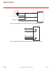
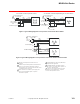
Figure 1 Typical Wiring Diagrams for Proportional Control 24 Vac Basic Models.
1
2
6
24 Vac Transformer
or 20-30 Vdc
Line
Volts
Control Signal
Feedback Signal
(-)
(+)
(-)
(+)
2
6
Blk
Red
Com
Hot (+DC)
Yel/Blk
AI
AO
Violet
Blk
Red
Yel/Blk
Violet
AI
AO
Hot (+DC)
Com
MS4D-xxx3-xx0
MS4D-xxx3-xx0
3
3
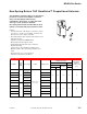
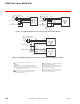
Figure 2 Typical Wiring Diagrams for Proportional Control 24 Vac Models Wired In Parallel.
1
2
3
4
5
6
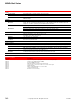
Provide overload protection and disconnect as
required.
Actuators may be wired in parallel. All actuator black
wires are connected to the transformer Common
and all red wires are connected to the Hot lead. Power
consumption must be observed.
If the controller uses a full-wave power supply and
does not provide isolated outputs, a separate
transformer is required.
A field-supplied 500 ohm resistor (AM-708) is
required for this application.
On MS4D-xxx3-x60 (4-20 mAdc) models a
500 resistor is incorporated in the product. Do
not use an external resistor.
Cable on some models contains more wires
than are used in applications. Only those
wires actually used are shown.