
Accessory List


MS40-7043, MS41-7073, MS41-7153
170
© Copyright 2006 TAC. All Rights Reserved. F-27382-1
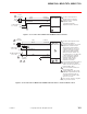
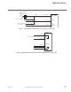
Hot (DC)
MS40-7043-MP
MS40-7043-MP5
24 Vac
Transformer
Red
Black
Common
1
Line
Volts
(-)
(+)
Control Signal
4 to 20 mA
Yellow/Black
AI
Blue
AO
(-)
(+)
Auxiliary Power
+20 Vdc
25 mA
1 Provide overload protection and
disconnect as required.
2 For unison operation in 4 to 20 mA
applications, actuators may be
wired in series and mounted on
separate shafts. Also, up to four
actuators, mounted on separate
shafts may be wired in parallel.
With four actuators wired to one
500 ohm resistor, a +2% shift of the
control signal may be required.
Power consumption and input
impedance limits must be
observed. Actuator input
impedance is 80 kohm.
3 To reverse actuator rotation, use
the reversing switch.
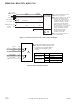
2
3
L R
Common
Grey
Green/Yellow
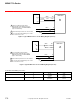
Figure 3 6 to 9 Vdc Proportional Control with 20 Vdc Power Output.
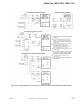
1 For end position indication, interlock control
fan startup, etc., MS40-7XX3-50X models
incorporate one or two built-in auxiliary
switches. See Specifications section
for details.
1
Com
NO
NC
Com
NO
NC
Yellow/White
Yellow
Orange
Orange/White
Violet
Violet/White
A
B
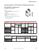
Figure 4 Optional Auxiliary Switches.
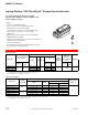
Model # Switch Switch Type
MS40-7153-502
MS40-7073-502
A Adjustable, 25° - 85°
B Fixed at 5°
MS40-7043-501
A Adjustable, 0 - 1 scale
BNone