
Accessory List
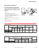
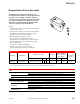


MS40-7043, MS41-7073, MS41-7153
F-27382-1 © Copyright 2006 TAC. All Rights Reserved. 167
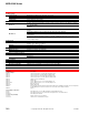
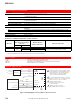
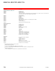
Specifications
Inputs
Control signal Proportional, 6 to 9 Vdc, 2 to 10 Vdc, or 4 to 20 mA with 500 ohm resistor.
Power All 24 Vac circuits are Class 2. Refer to Model Chart for AC and DC ratings. Half wave device.
Connections
MS41-7073, MS41-7153: 3 ft. (0.9 m) long, appliance cables, 1/2 in. conduit connectors. For M20
metric conduit, use AM-756 adaptor. MS40-7043: 3 ft. (0.9 m) long, plenum-rated cables, 1/2 in.
conduit connectors. For M20 metric conduit, use AM-756 adaptor. MS40-7043: 3 ft. (0.9 mm ) plenum
rated cable.
Outputs
Motor Type Brushless DC.
Electrical
Internal Power Supply: 20 Vdc, 25 mA.
Control Mode: Switch provided for selection of direct acting or reverse acting control mode.
Mechanical
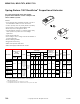
Position Indicator: MS40-7043: Visual indicator, 0 to 1 (0 is the spring return position).
MS41-7073, MS41-7153: Pointer (-5 to 90°) and scale are provided for position indication (-5 is normal
or spring return position).
Direction of rotation: CW or CCW rotation is available through reversible mounting.
Damper shaft clamp: Direct coupled using a through hole output hub.
Environment
Temperature limits
Shipping and storage: -40 to 160°F (-40 to 71°C) ambient.
Operating: -22 to 140°F (-30 to 60°C).
Humidity 5 to 95% RH, non-condensing.
Locations NEMA 1, NEMA 2 (IEC IP54) with conduit in the down position.
Agency Listings
UL
UL-873, Underwriters Laboratories Listed (File #9429 Category: Temperature-Indicating and
Regulating Equipment).
European Community EMC Directive (89/336/EEC). Low Voltage Directive (72/23/EEC).
CSA Canadian Standards C22.2 No. 4-93.
Australia
This product meets requirements to bear the C-Tick mark according to the terms specified by the
Communications Authority under the Radio Communications Act 1992.
General Instructions Refer to F-26645.