
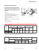
Accessory List
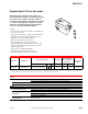


MS-22353
F-27382-1 © Copyright 2006 TAC. All Rights Reserved. 165
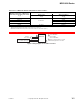
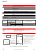
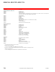
Figure 2 Wiring Diagram for 2 to 10 Vdc Proportional Control.
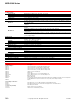
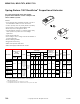
Power and Control Wiring Color Codes.
Actuator Label Description
Wire Codes
Color Only
(Current Models)
Colors with Numbers
(Older Models
a
)
a
Actuator models manufactured prior to date code 991X (e.g. 9910, 9911, etc.) have multi-color, numbered wires.
Actuator
Power
Earth Earth Ground Green Green (—)
24 H 24 Vac Black Black (1)
24 G 24 Vac Red Red
b
(2)
b
Actuator extend wire may be violet on some models.
Proportional
Control
Signals
+ VDC (IN) 2 to 10 Vdc Input White White/Green (3)
- COMMON DC Common Ground Orange White/Orange (4)
+ mADC (IN) 4 to 20 mADC Input Brown White/Brown (6)
Feedback
Control
Signal
+ VFB Actuator Feedback Blue White/Blue (5)
L1
L2
24H
24G
24 Vac
Transformer
Black
Red
Green
24H
24G
Brown
Blue
Orange
White
Unused
(wire nut)
0 to 10 Vdc Controller
(+) 0 to 10 Vdc Output
(-) Common
Earth
(+) mA DC IN
(+) VDC IN
(-) Common
(+) VFB
Feedback Signal
MS-22353
1 The MS-22353 actuator contains a half-wave rectifier power supply.
When connecting multiple devices to a common transformer
connect 24H and 24G with half-wave rectifier or isolated power
supplied devices, only. Refer to EN 206 (F-26363).
2 For actuator models manufactured prior to date code 990X (e.g. 9904, 9905, etc.),
see "Power and Control Wiring Color Codes" for wire color numbers.
3 Optional connection for controllers with feedback input. If unused, wire nut.
2
Feedback Input
3
1