
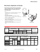
Accessory List


MP-3xx Series, MP-4xx Series, MP-2xxx Series, and MP-4xxx Series
F-27382-1 © Copyright 2006 TAC. All Rights Reserved. 141
Accessories
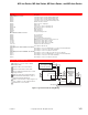
Typical Applications
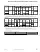
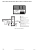
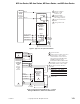
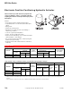
Figure 1 Typical Reversible Floating Wiring.
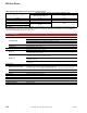
Model No. Description
Damper linkage accessories
AM-111 Crank arm for 5/16 in. (7.9 mm) diameter damper shaft.
AM-112 Crank arm for 3/8 in. (9.5 mm) diameter damper shaft.
AM-113 Crank arm for 1/2 in. (12.7 mm) diameter damper shaft.
AM-115 Crank arm for 7/16 in. (11.1 mm) diameter damper shaft.
AM-116 Splined crank arm for actuator.
AM-122 Linkage connector, straight type.
AM-123 Damper clip.
AM-125 5/16 x 20 in. (7.9 mm x 0.5 m) damper rod.
AM-125-048 5/16 x 48 in. (7.9 mm x 1.2 m) damper rod.
AM-132 Ball joint connector.
AM-161 Damper linkage kit.
AM-161-1 Damper linkage kit.
AM-301 90 degree mounting bracket.
Miscellaneous actuator accessories
AM-321 Two step switch kit.
AM-332 Potentiometer kit.
AM-341 Four step switch kit.
AM-342 Two step switch and potentiometer kit.
AM-363 NEMA 4 gasket kit for non-spring return actuators only.
CP-8301 Electronic drive, voltage input 1 to 20 Vdc.
CP-9301 Electronic drive, voltage input 6 to 9 Vdc.
CP-9302 Electronic drive, voltage input 4 to 20 mAdc.
TOOL-201 Calibration kit for TAC System 8000.
TOOL-209 135 Ω slidewire calibration kit.
Valve linkage for 50 lb.-in. minimum, 180° actuator.
AV-391 Valve linkage for 1/2 to 2 in. VB-7XXX and 1/2 to 1-1/4 in. discontinued VB-9XXX.
AV-392 Valve linkage for 1-1/2 and 2 in. discontinued VB-9XXX.
AV-395 Valve linkage for 2-1/2 to 4 in. VB-9213 or VB-9313.
Valve linkage for 130 lb.-in. minimum, 180° actuator.
AV-352 Valve linkage for 2-1/2 to 6 in VB-9213 or VB-9313, 4 to 6 in. VB-9323.
AV-393 Valve linkage for 1/2 to 2 in. VB-7XXX and 1/2 to 1-1/4 in. discontinued VB-9XXX.
AV-394 Valve linkage for 1-1/2 and 2 in. discontinued VB-9XXX.
AV-396 Valve linkage for 2-1/2 to 4 in. VB-9213 or VB-9313.
1 Terminals 1,5, & 6 are used for built-in
auxiliary switch.
2 Rotates CW or Lowers Valve Stem.
3 Rotates CCW or Raises Valve Stem.
4 These terminal are marked L1 & L2 on line
voltage actuators.
5 Remove green wire to unground actuator.
6 SPDT Neutral Off Switch may be used on
manual positioning applications.
7 Switch control circuit is 0.5 amp at approx. 24
Vac on either low or line voltage actuators.
8 Install under cover of actuator.
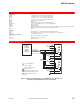
4
5
2
3
8
3
6
7
4
3
MP-300
MP-400
MP-400-600
MP-2000-500
MP-4000
Series
Actuator
H
G
2
X
Green
AC Supply
SPDT Floating Control
CYZR-818
Arc Suppressor
purchased separately
White
Blue
Red