
Accessory List
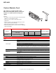


MM-400 Series, MM-500 Series, MMR-400 Series, MMR-500 Series
134
© Copyright 2006 TAC. All Rights Reserved. F-27382-1
Specifications
Optional MMC series control modules
Control signal
The MMC series control module determines the control signal (order separately).
MMC-90: 135 Ω slidewire.
MMC-401: TS-5721-102 temperature sensor. The economizer module can only be used with the
MM-500 series actuator.
MMC-420: 4 to 20 mAdc.
MMC-421: 2 to 20 mAdc.
MMC-468: Two position SPST or SPDT.
MMC-8000: 0 to 20 mAdc or 0 to 20 Vdc.
Power req. 24 Vac Class 2 (+10/-15%) 50/60 Hz power supply required.
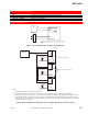
Connections
Control: 1/4 in. quick-connect (spade lug) terminals.
Auxiliary switch: Screw terminals.
Modular actuator outputs
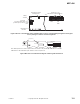
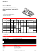
Output shaft
Description: Dual 3/8 in. (9.5 mm) square shafts with 3/64 x 3/16 in. (1.2 x 4.8 mm) keyways and
#8-32 1/2 in. (12.7 mm) tapped hole in each end of shaft.
Rotation: Shaft rotation as viewed from the front of the motor. The front of the motors defined as the
left end when facing the auxiliary switches adjustments.
Nominal Damper Area: Actuator sizing should be done in accordance with damper manufacturer’s
specifications.
Dead weight load 200 lb. (90.9 kg) either end.
Shaft rotation Factory set at maximum 160°. Adjustable to 75, 90, or 110°.
Factory setting Shaft position for shipping is set at the full CCW position.
Environment
Ambient temperature limits
Shipping and storage: -40 to 160°F (-40 to 71°C).
Operating: MMR/MM-400/500, -40 to 140°F (-40 to 60°C); MMR/MM-400/500 with AM-231.
Transformer Kit, -40 to 130°F (-40 to 54°C).
Humidity 5 to 95% RH, non-condensing.
Vibration Maximum 1 G in any plane.
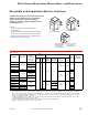
Locations
NEMA Type1 when mounted in any position; NEMA 3R when mounted in vertical position up only,
AM-232 gasket kit (factory installed) and Appleton ST-50 flexible metal conduit connection with
STG-50 gasket field installed.
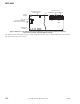
Construction
Housing: Glass reinforced thermoplastic (PET) UL-94-5V flame rated housing material to meet
UL-465 requirements for air plenum mounting, plated steel base. One (1) 1/2 in. conduit knock-out on
two sides of housing.
Dimensions 7-1/2 H x 5-9/16 W x 5-5/8 D in. (184 x 141 x 143 mm).
General Instructions Refer to F-23347.