
Accessory List


MFC-8000
F-27382-1 © Copyright 2006 TAC. All Rights Reserved. 131
Typical Applications
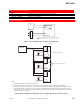
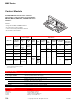
Figure 1 Typical Wiring Diagram for MF-63123 with MFC-8000.
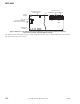
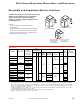
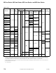
Figure 2 MF-63123 and MFC-8000 Wiring for Three Units Operating in Unison and/or Sequence.
Specifications (Continued)
Agency Listings
UL File E9429 Temperature Indicating and Regulating Equipment.
CUL Canadian Standard C22.2 #24-93
European Community EMC Directive (89/336/EEC).
MFC-8000
MF-63123
2
3
H
G
(+) Vdc
(-) Vdc
Vdc
Controller
L1
L2
1
1
Factory installed in actuator. Set for 6 to 9 mAdc control signal. Consult
MFC-8000General Instructions, F-25124 for further information.
2
3
G
H
T4 (G)
T5 (H)
MFC-8000
MF-63123
6 to 9 Vdc
Controller
Transformer
1
2
3
G
H
T4 (G)
T5 (H)
MFC-8000
MF-63123
Transformer
1
2
3
G
H
T4 (G)
T5 (H)
MFC-8000
MF-63123
Transformer
(–) Vdc Input (Common)
(+) Vdc Input
(+) Vdc
Factory Set for 6 to 9 Vdc D.A.
(–) Vdc
24 Vac
24 Vac
24 Vac
1
Notes:
1. A separate transformer is required for each actuator.
2. Unison operation of the actuators is shown. Connect the (+) Vdc controller signal to terminal 2 on the MFC-8000.
3. For sequence operation of the actuators, change the span and extend point settings of the MFC-8000. For example, set the
span and extend point of actuator #1 for .25 to 3.25 Vdc (.25 Vdc extend point and 3 Vdc span) set span and extend point of
actuator #2 for 3.5 to 6.5 Vdc (6.5 extend point and 3 Vdc span) and set span and extend point actuator #3 for 6.75 to 9.75 Vdc
((.75 extend point and 3 Vdc span).