
Accessory List

MF4E-60x3x Series
122
© Copyright 2006 TAC. All Rights Reserved. F-27382-1
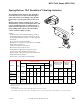
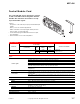
Typical Applications
Typical
Floating
Controller
1
2
3
24 Vac
Transformer
Line
Voltage
MF4E-60430-100
MF4E-60830-100
Common
CW
CCW
CCW
COM
CW
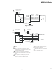
1 Provide overload protection and a
disconnect as required.
2 Actuators may be wired in parallel only
if they have the same rotational speed
(stroke timing). When doing so, be sure
to obser
ve power consumption limits.
3 To increase actuator life, design the
system with a time-out feature that
removes power from the actuator
between uses. For example, such a
device may stop controller outpu
t after
powering the actuator in one direction
for 3 minutes or more.
Blue
Black
Yellow/Black
4
CW/CCW drive direction is as viewed
from the top of the actuator.
4
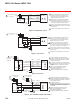
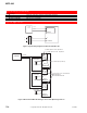
Figure 1 Floating Point Control Wiring Diagram.
2
3
Line
Voltage
CW
CCW
MF4E-60430-100
MF4E-60830-100
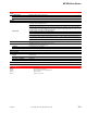
1 Provide overload protection and a
disconnect as required.
2 Actuators may be wired in parallel only
if they have the same rotational speed
(stroke timing). When doing so, be sure
to observe power consumption limits.
3 To increase actuator life, design the
system with a time-out feature that
removes power from the actuator
between uses. For example, such a
device may stop con
troller output after
powering the actuator in one direction
for 3 minutes or more.
24 Vac
Transformer
Common
1
Controller
Hot
Common
CCW
COM
CW
Blue
Black
Yellow/Black
CW/CCW drive direction is as viewed
from the top of the actuator.
4
4
Figure 2 Triac Source Wiring Diagram.
2 3
4
Line
Voltage
CW
CCW
MF4E-60430-100
MF4E-60830-100
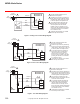
1 Provide overload protection and a
disconnect as required.
2 Actuators may be wired in parallel only
if they have the same rotational speed
(stroke timing). When doing so, be sure
to observe power consumption limits.
3 The Common connection from the
actuator must be connected to the Hot
connection of the controller.
4 To increase actuator life, design the
system with a time-out feature that
removes
power from the actuator
between uses. For example, such a
device may stop controller output after
powering the actuator in one direction
for 3 minutes or more.
24 Vac
Transformer
Common
1
Controller
Hot
Common
CCW
COM
CW
Blue
Black
Yellow/Black
CW/CCW drive direction is as viewed
from the top of the actuator.
5
5
Figure 3 Triac Sink Wiring Diagram.