
Accessory List
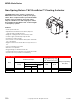

MF4D-x033 Series
F-27382-1 © Copyright 2006 TAC. All Rights Reserved. 119
MF4D-x033-x00
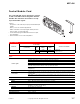
Red
Black
Common
Hot (+DC)
1
Line
Volts
Controller
Blue
Yellow/Black
Hot
Common
3
Drive CW
Drive CCW
24 Vac Transformer
or 20 to 30 Vdc
Violet
AO
4
5
Feedback Signal
2 to 10 Vdc
(-)
(+)
6
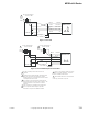
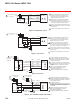
Figure 3 Triac Sink.
1
Line
Volts
24 Vac Transformer
or 20 to 30 Vdc
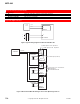
MF4D-x033-x00
Red
Black
Common
Hot (+DC)
1
Line
Volts
Controller
Blue
Yellow/Black
Hot
Common
Drive CW
Drive CCW
24 Vac Transformer
or 20 to 30 Vdc
Violet
AO
4
5
Feedback Signal
2 to 10 Vdc
(-)
(+)
6
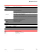
Figure 4 Triac Sink With Separate Transformers.
1
2
3
4
5
Provide overload protection and disconnect as
required.
Actuators may be wired in parallel. All actuator black
wires are connected to the transformer Common
and all red wires are connected to the Hot lead. Power
consumption must be observed.
The Common connection from the actuator must be
connected to the Hot connection of the controller. The
actuator Hot must be connected to the controller
Common.
If the controller uses a full-wave power supply and
does not provide isolated outputs, a separate
transformer is required. See EN206, F-26363.
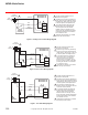
Cable on some models contains more wires
than are used in applications. Only those
wires actually used are shown.
CW/CCW drive direction is as viewed from
the top (removable cover) side.
6