
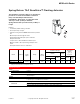
Accessory List


MF41-6343
F-27382-1 © Copyright 2006 TAC. All Rights Reserved. 111
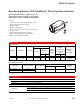
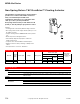
Non-Spring Return TAC DuraDrive
®
Floating Actuator
Model Chart
Specifications
For non-spring return applications that require
floating control of dampers and valves in HVAC
systems.
Features:
• Direct mount to round or square damper shaft.
• 300 lb.-in. (34 N-m) torque rating.
• Overload protection throughout rotation.
• Oil immersed gear train provides continuous lubrication.
• NEMA 4 housing (IEC IP56).
• Manual override to allow positioning for installation and
manual operation.
• Provide floating point control (drive open-hold-drive
closed).
Damper Actuators.
Model No.
Damper Shaft
Size
a
a
Optional AM-753 damper shaft mounting clamps for 5/8 in. square or 3/4 to 1 in. round shafts.
Actuator Power Input
SPDT
Auxiliary
Switches
Approximate
Timing in
Seconds @ 70°F
(21°C) with No
Load
Output Torque
Rating
lb.-in. (N-m)
Voltage
5-/60 Hz
Watts
VA
Running Holding
VA W Minimum
Maximum
Stall
MF41-6343
3/8 to 1/2 in.
round or square
24 Vac
± 20%
3.8 7.1 3.6 No <145 300 (34) 600 (68)
Valve Actuator plus LInkages.
Model No.
a
a
Refer to Valve Catalog, F-27384, for correct applications.
Linkage (included)
Voltage 50/60
Hz
Running
Holding
VA
SPDT Aux.
Switches
W
VA
MF41-6343-230 AV-609 24 Vac ± 20% 3.8 7.1 3.6 No
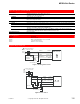
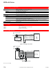
Inputs
Control signal SPDT floating control input, triacs (500 mA rated) or 2 SPST contacts.
Power Refer to Model Chart. All 24 Vac circuts are Class 2.
Connections 24 in. (61 cm) appliance cables. Conduit connector for M20 metric conduit use AM-756 adapter.
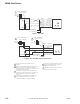
Outputs
Motor Type Brushless DC.
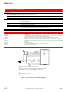
Mechanical
Direction of rotation: CW or CCW rotation is available through reverse mounting.
Dual shaft clamp: Direct coupled using a through hole output hub. 3/8 to 1/2 in. round or square shafts
standard.
Position indicator: Pointer and scale numbered from 0 to 95°. Stroke 93° ±1°. See Accessories for
larger shaft sizes.
F41
-
6343
US