
Accessory List
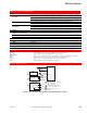

MF40-7043 Series, MF41-7073 Series, MF41-7153 Series
F-27382-1 © Copyright 2006 TAC. All Rights Reserved. 103
Typical Applications
MF41-7153
MF41-7073
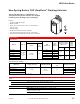
24 Vac Transformer or
22 to 30 Vdc
Red
Black
Common
1
+ Hot
Line
Volts
Blue
Drive CW
Drive CCW
Yellow/Black
1 Provide overload protection and
disconnect as required.
2 Actuators may be wired in parallel.
All actuator black wires are
connected to the transformer
common and all red wires are
connected to the hot lead. Power
consumption must be observed.
3 If the controller uses a full-wave
power supply and does not
provide isolated outputs, a
separate transformer is required.
See EN206, F-26363 for details.
4 As viewed from Left (L) side.
2
Green/Yellow
Typical
Floating
Controller
3
4
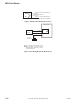
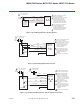
Figure 1 Typical Wiring Diagram For Floating Actuator.
MF41-7153
MF40-7043
MF41-7073
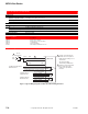
24 Vac Transformer or
22 to 30 Vdc
Red
Black
Common
Hot
1
Line
Volts
Controller
Blue
2
Yellow/Black
Hot
Common
3
Green/Yellow
Drive CW
Drive CCW
1 Provide overload protection and
disconnect as required.
2 The Common connection from
the actuator must be connected
to the Hot connection of the
controller. The actuator Hot
must be connected to the
controller Common.
3 If the controller uses a full-
wave power supply and does
not provide isolated outputs, a
separate transformer is
required.
4 As viewed from Left (L) side.
4
Figure 2 Typical Wiring Diagram with Triac Sink.
Red
Black
Common
Hot
Controller
3
2
Drive CCW
Yellow/Black
1
Line
Volts
Hot
Common
Blue Drive CW
24 Vac Transformer
or 22 to 30 Vdc
1
Line
Volts
Green/Yellow
MF41-7153
MF40-7043
MF41-7173
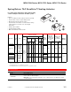
1 Provide overload protection
and disconnect as required.
2 Actuators may be wired in
parallel. All actuator black
wires are connected to the
transformer common and all
red wires are connected to the
hot lead. Power consumption
must be observed.
3 The actuator Hot must be
connected to the controller
Common.
4 If the controller uses a full-
wave power supply and does
not provide isolated outputs, a
separate transformer is
required.
4
24 Vac Transformer
or 22 to 30 Vdc
5
5 As viewed from Left (L) side.
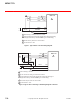
Figure 3 Typical Wiring Diagram with Triac Sink and Separate Transformers.