
Accessory List
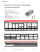

MF40-7043 Series, MF41-7073 Series, MF41-7153 Series
102
© Copyright 2006 TAC. All Rights Reserved. F-27382-1
Accessories
Specifications (Continued)
Outputs
Motor Type Brushless DC.
Electrical
One auxiliary switch available with MF40-7043-501, SPDT 6A resistive @ 24 Vac, adjustable 0 to 95°
(0 to 1 scale). UL Listed, switch meets VDC requirements for 6 (1.5)A, 24 Vac.
Two auxiliary switch available with MF40-7153-501 or MF40-7073-502, SPDT 7A resistive @ 24 Vac,
one fixed @ 5° and one adjustable 0 to 95°. UL Listed, switch meets VDC requirements for 6 (1.5)A,
24 Vac.
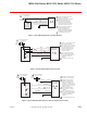
Position feedback voltage “AO”: 2 to 10 Vdc (maximum 0.5 mA) output signal for position feedback or
operation of up to four slave actuators.
Control mode: Switch provided for selection of direct acting or reverse acting control mode on
proportional models.
Timing: Refer to Model Chart.
Mechanical
Output torque rating: Refer to Model Chart.
Position Indicator: MF40-704X: Visual indicator, 0 to 1 (0 is the spring return position).
MF40-707X, MF40-715X: Pointer (-5 to 90°) and scale are provided for position indication (-5 is
normal or spring return position).
Stroke: Refer to Model Chart.
Environment
Ambient Temperature limits
Shipping and storage: -40 to 160°F (-40 to 71°C).
Operating: -22 to 140°F (-30 to 60°C).
Humidity 5 to 95% RH, non-condensing.
Locations
MF40-704X: NEMA 2 (IEC 1P54).
MF40-707X: NEMA 1, NEMA 2 (IEC IP54) with conduit in the down position.
MF40-715X: NEMA 1, NEMA 2 (IEC IP54) with conduit in the down position.
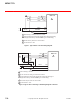
Dimensions
MF40-7043: 6-51/64 H x 4 W x 3-1/2 D in. (170 x 100 x 90 mm).
MF41-7xxx: 10-1/2 H x 4 W x 3-1/2 D in. (270 x 100 x 90 mm).
Agency Listings
UL
UL-873, Underwriters Laboratories Listed (File #9429 Category: Temperature-Indicating and
Regulating Equipment).
European Community EMC Directive (89/336/EEC). Low Voltage Directive (72/23/EEC).
CSA Canadian Standards C22.2 No. 4-93.
Australia
This product meets requirements to bear the C-Tick mark according to the terms specified by the
Communications Authority under the Radio Communications Act 1992.
General Instructions Refer to F-26644.
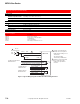
Model No. Description
MF40-7043, MF40-7073, MF40-7153
AM-673
a
a
Drill appropriate mounting holes where needed.
Mounting bracket.
AM-674 Weather shield.
AM-675 Weather shield base.
AM-676 Universal shaft extension, approximately 9-1/2 in. long (242 mm) for use on 3/8 to 11/16 in. (10 to 17 mm)
round shafts, 3/8 to 9/16 in. square shafts. (AM-753 clamps required).
AM-756 Metric conduit adaptor M20 x 1.5 to 1/2 in. NPT (two per package).
AM-714 Weather shield.
MF40-7073, MF40-40-7153
AM-671
abcd
b
AM-693 crank arm kit required.
c
Cannot be used with Mx40-634x or Mx40-717x series actuators.
d
The large "C"-shaped clamps included in AM-693 crank arm kit are required for mounting the actuator. Drill appropriate mounting holes where needed.
Mounting bracket.
AM-672
abcd
Mounting bracket.
AM-686 Position indicator.
AM-687 V-clamp.
AM-689 Rotation limiter.
AM-690 Crank arm.
AM-691 Crank arm.
AM-692 V-bolt.
AM-693
ef
e
Use the self-tapping screws and flat washers provided in kit to mount actuator.
f
AM-692 V-bolt kit required.
Crank arm kit.
AV-602 Valve linkage for VB-7xxx 1 to 2 in.
AV-607 Valve linkage VB-9xxx 2-1/2 to 4 in.
MF40-7043
AM-709 Position indicator and stroke limiter.
AM-710 V-clamp.
AM-711 Crank arm adaptor kit.
AM-712
e
Crank arm adaptor kit
AM-713
e
Bracket.
AM-715
e
Crank arm adaptor kit.
AV-605 Valve linkage for VB-7xxx.