
Accessory List
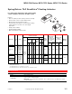
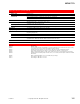

MF-631x3 Series
100
© Copyright 2006 TAC. All Rights Reserved. F-27382-1
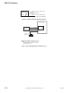
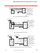
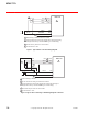
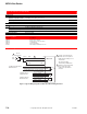
Figure 2 Auxiliary Switch Models MF-631x3-500.
Figure 3 Basic Wiring Diagram for MF-63123-201.
NO
NC
Brown
Red/White
Orange
Closed at extended end
Common
Closed at retracted end
Factory settin
g
s are adjustable.
MF-63123-201
1
2
3
(+) Vdc
(-) Vdc
MFC-8000
Vdc
Controller
24 Vac
Transformer
H
G
L2
L1
1 Factory installed in actuator. Set for 0 to 10
Vdc control signal, reverse action. Consult
MFC-8000 General Instructions, F-25124
for further information.