
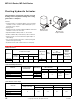
Accessory List


MF-631x3 Series
98
© Copyright 2006 TAC. All Rights Reserved. F-27382-1
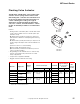
Floating Valve Actuator
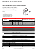
Model Chart
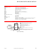
Specifications
This valve actuator is a non-spring return actuator
compatible with floating and optional proportional
controllers.
Features:
• Floating actuator controlled by SPDT floating controller (drive
open-hold-drive closed) or a DDC controller with equivalent
control action (contact or triac).
• Optional control module cards for proportional control
(MF-63123 only): MFC-8000 for Vdc and MFC-420 for 4 to 20
mAdc.
• 210 lbs minimum output force with automatic load limit.
• Wide operating ambient range of 0 to 140°F (-18 to 60°C).
• Synchronous motor assures accurate stroke timing.
• MF-63123 series available with position feedback
potentiometer.
• Self-adjusting travel and position feedback potentiometer
mechanisms.
• Manual override operation with automatic release.
• Adjustable SPDT auxiliary switch on -500 models.
• Rugged construction: Die cast housing, double thread 1/2 in.
dia. stainless steel jackscrew, roller thrust bearings, and all
metal gear train.
• Integral linkage for 1/2 to 2 in. VB-7xxx and VB-9xxx 1/2 to
1-1/4 in. valves. Optional linkage for 2-1/2 to 5 in. VB-8xxx
valves, 2-1/2 to 4 in. VB-931x and discontinued 1-1/2 to 4 in.
VB-9xxx (except VB-9323 2-1/2 to 4 in.).
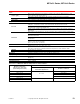
Model No.
Actuator Power Input
Feedback 15K Ω
Pot.
Aux. Switch
Voltage (+10%/ -15%) Hz VA Watts
MF-63103
24 Vac 50/60 6 7
No
No
MF-63103-500 Yes
MF-63123
a
a
Feedback potentiometer cannot be used when MFC control module card is installed
Yes No
MF-63123-201
b
b
MF-63123 with MFC-8000 0 to 10 Vdc reverse action factory set.
No
Yes
MF-63123-500
a
Yes
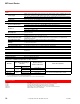
Inputs
Control signal
SPDT floating control contacts or 2 SPDT control contacts: Minimum rating of 1/2 amp at 24 Vac
inductive load.
Triacs: DDC controller must be able to switch 1/2 amp inductive load (200 Vac minimum).
Power Refer to Model Chart.
Connections Coded screw terminals.
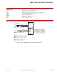
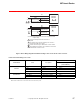
MF
-
631
x
3
Series
US