™ RQ 2300 Series REFERENCE QUALITY COMPACT CONSOLES O P E R AT I N G G U I D E
Intended to alert the user to the presence of uninsulated “dangerous voltage” within the product’s enclosure that may be of sufficient magnitude to constitute a risk of electric shock to persons. Intended to alert the user of the presence of important operating and maintenance (servicing) instructions in the literature accompanying the product. CAUTION: Risk of electrical shock — DO NOT OPEN! CAUTION: To reduce the risk of electric shock, do not remove cover. No user serviceable parts inside.
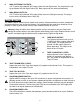
ENGLISH RQ™ 2300 Compact Console The all new RQ™ 2300 Series mixer is a compact unit that can be used in sound reinforcement or recording applications. Its low noise design and extensive list of features make it the ideal mixing console for almost any application. NOTE: This manual covers all RQ™ 2300 Series mixers. Differences in the various models are noted where applicable. GENERAL DESCRIPTION: All RQ 2300 Series mixers share the same master section.
yellow must be connected to the terminal which is marked by the letter E, or by the earth symbol, or colored green or green and yellow. (2) The wire which is colored blue must be connected to the terminal which is marked with the letter N, or the color black. (3) The wire which is colored brown must be connected to the terminal which is marked with the letter L or color red. 2. POWER: This is the mixer’s main power switch. To turn the power on place the switch in the (|) position.
8. MAIN LEFT/RIGHT OUTPUTS: 1/4" TS and a fully balanced XLR output of the Left and Right mixes. The output level is set by the Master Left and Right Faders (35). Both outputs can be used simultaneously. 9. MAIN MONO OUTPUTS: 1/4" TS and a fully balanced XLR output of the mono mix (left/right summed). The output level is set by the Master Mono Fader (36).
16. HEADPHONE OUTPUT: This stereo jack (TRS) provides the signal to drive stereo headphones. The level is set by the Headphone Level control (17). Tip= Left, Ring= Right, Shield= Ground. 17. HEADPHONE/PFL LEVEL: Adjusts the level of the Headphone Output. The source changes from the L-R output to the PFL mix whenever the PFL is active. 18. PFL ACTIVE: This LED blinks when the PFL is active and its signal is overriding the standard L-R mix in the Headphone and at the L/R meters.
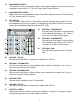
28. EFFECTS 2 SEND: Adjusts the level of the Effects 2 mix sent to the Effects 2 Output (5). Unity gain is at the center detent position and +10 dB of gain in maximum. 29. LED METERS: Two 12-segment LED arrays monitor the levels of the main L/R outputs. The 0 dB reference level corresponds to +0 dBu at the 1/4" jacks and XLR. (See 8.) 30. MONITOR PEAK LED: Indicates that the monitor mix level is nearing the overload point. It illuminates at +19 dBu and warns that gain or EQ boost should be reduced.
INPUT CHANNELS This section describes the many features found on the input channels. The RQ Series mixer you have purchased utilizes multiple channel configurations. Some channels do differ from others. It is important that you recognize these differences in order to take advantage of each channel’s features and avoid confusion. Channel Functions 1 — 6 (RQ 2310), 1 — 10 (RQ 2314) and 1 — 14 (RQ 2318): 37.
44. LOW EQ: A shelving type of active tone control that varies the bass frequency levels +/-15 dB at 70 Hz. It will add depth to thin signals or clean up muddy ones. 45. MON 1: Adjusts the level of the channel signal (pre-EQ) that is added to the Monitor 1 mix. This is a mono mix of the left and right signals in the stereo channels. The center detent is the unity gain position. 46. MON 2: Adjusts the level of the channel signal (pre-EQ) that is added to the Monitor 2 mix.
54. FADER: Channel output level control. The level of the channel can be adjusted from off to +10 dB of gain. The optimum setting is the “0” (unity gain) position. Channel Functions 5 — 6 (RQ 2310), 9 — 10 RQ 2314 and 13 — 14 (RQ 2318): In these two channels all controls are identical to the previous channels with the exception of the insert jack. It is replaced by pad and polarity switches. 55. PAD: When pressed it attenuates the input signal by 20 dB.
RQ™ 2300 COMPACT CONSOLE Specifications: Input Specifications: Function Microphone (150 ohms) Line Input (10 k ohms) Input Z (ohms) Min Input Gain Settings 2.2 k Max. Gain (58 dB) Min. Gain (10 dB) 10 k Min** Input Levels Nominal* Max Bal/ Connector UnBal. -78 dBu -58 dBu -37 dBu -31 dBu -10 dBu +10 dBu Max. Gain (38 dB) -58 dBu -38 dBu -17 dBu Min. Gain (-10 dB) -10 dBu 10 dBu +31 dBu +21 dBu Unbal.
Output Specifications: Function Main L/R Monitors Mono Minimum Load Ohms Min** 600 0 dBu +21 dBu Bal. 1/4" TRS: Tip (+), Ring (-) Sleeve Ground 0 dBu +21 dBu Bal. XLR: Pin 1 Ground Pin 2 (+), Pin 3 (-), (Bal.) 0 dBu +21 dBu Bal. 1/4" TRS: Tip (+) Ring (-), Sleeve Ground 0 dBu +21 dBu Bal. XLR: Pin 1 Ground, Pin 2 (+), Pin 3 (-), (Bal.) 0 dBu +21 dBu Bal. 1/4" TRS: Tip (+), Ring (-), Sleeve Ground 0 dBu +21 dBu Bal. XLR: Pin 1 Ground Pin 2 (+), Pin 3 (-), (Bal.
Gain: Mic Input Gain Adjustment Range: Mic Input to L/R Balance Output Mic Input Longest Path 10 dB to 58 dB 78 dB (Max. Gain) 91 dB (Max. Gain) Line Input Gain Adjustment Range: Line Input to L/R Bal. Output Line Input to longest Path -10 dB to 38 dB 60 dB (Max. Gain) 73 dB (Max. Gain) Stereo Line Input Gain Adjustment Range Stereo Line Input to L/R Balance Output Stereo Line Input Longest Path 10 dB 36 dB (Max. Gain) 46 dB (Max. Gain) Aux Return to L/R Balance Output 34 dB (Max.
Equivalent Input Noise (EIN): -129 dBu (Input terminated with 150 ohms) Crosstalk: >70 dB Adjacent Input Channels @ 1 kHz >70 dB Left to Right Outputs@ 1 kHz Common Mode Rejection Ration (Mic Input): 50 dB min. (20 Hz to 20 kHz) 70 dB type @ 1 kHz Meters: 12 segment, peak reading (0 dB=0 dBu) Signal/Overload Indicators: Red LED lights 2 dB below clipping Dimensions (H x W x D): RQ 2310: 4.450" x 16.158" x 18.930" (11.30 cm x 41.01 cm x 48.08 cm) RQ 2314: 4.450" x 20.158" x 18.930" (11.30 cm x 51.20 cm x 48.
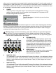
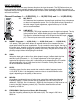
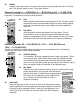
CH. A ® SP 2G ™ ® Output CS 800s CH. B Return Send DeltaFex Input ™ EQ 215fx Return Send ® SP 112M ™ Input ® ™ CD Player EQ 215fx CS 800s CH. B Output CH.
INSERT RQ 2310 CH 1—4 RQ 2318 CH 1—12 RQ™ 2300 Series LEVEL DIAGRAM
RQ™ 2300 Series BLOCK DIAGRAM
E S PA Ñ O L Consola Compacta RQ™ 2300 La nueva mezcladora de la Serie RQ™ 2300 es una unidad compacta que puede ser usada para refuerzo de sonido o grabación. Su diseño de bajo ruido y extensa lista de características la hace una consola de mezcla ideal para casi cualquier uso. NOTA: Este manual cubre todas las mezcladoras de la serie RQ™ 2300. Las diferencias entre los modelos serán notadas cuando sea necesario.
1. Cable de Poder CA Esta conexión es para el cable de línea IEC (incluido), que provee poder CA a la unidad. Conecta 1 el cable de línea a este conector y a un suministro de CA propiamente aterrizado. Se puede dañar el equipo si se usa un voltaje e línea inapropiado. (Ver marcación de voltaje en la unidad). Nunca quites o 2 cortes la aguja de tierra que trae el conector del cable. Esta unidad incluye un cable de la marcación correcta.
alimentar un sistema externo de monitoreo. (La punta es positiva). El nivel de salida se ajusta con los controles e envío del canal individual de monitor 1 y por el fader maestro de monitor 1 (33). Ambas salidas pueden ser usadas de manera simultánea. 7. SALIDA MONITOR 2 Salida no balanceada TS 1/4" y salida balanceada XLR de la mezcla de monitor 2 diseñada para alimentar un sistema externo de monitoreo. (La punta es positiva).
13. NIVEL CINTA A I/D Ajusta el nivel de la señal de entrada de cinta (10) suministrada a la mezcla I/D. 14. SWITCH DE PODER PHANTOM Aplica poder de voltaje a 48VDC a lo conectores de entrada XLR para darle poder micrófonos que lo requieren. Si el poder phantom es usado, no conectes micros dinámico no balanceados u otros dispositivos a las entradas XLR que no puedan manejar este voltaje. (Algunos receptores inalámbricos pueden dañarse; consulta sus manuales).
24. 25. RETORNO 2 A MONITOR 2 Ajusta el nivel de la señal del retorno 2 (efectos) que es añadida a la mezcla de Monitor 2. Ésta es una mezcla monofónica de las señales izquierda y derecha. PAN DE RETORNO 2 Ajusta la posición del Retorno 2 en el campo estéreo I/D. 26. RETORNO 12A I/D Ajusta el nivel de la señal del Retorno 2 que es añadida a la mezcla I/D. 27. ENVÍO 1 DE EFECTOS Ajusta el nivel de la mezcla de Efectos 1 que es mandada a la salida de Efectos 1 (5).
35. FADERS MAESTROS IZQUIERDA/DERECHA Controles de nivel maestro I/D. Ya que las salidas de cinta y audífonos vienen de esta mezcla, también serán afectadas por su ajuste. Los niveles de salida son monitoreados por los medidores izquierdo y derecho. El ajuste óptimo para este control es la posición “0” (ganancia de unidad). 36. FADER DE SALIDA MONO Ajusta la salida de la señal Mono (I+D) que se encuentra en la salida Mono (9).
42. ECUALIZADOR DE MEDIOS Un control activo de tono tipo peak/notch de paso de banda que varía los niveles de frecuencia de rango medio. En los primeros seis canales de la RQ 2310 (primeros 10 canales-RQ 23144, primeros 14 canales RQ 2318), la frecuencia de aumento o corte es ajustado por el control de Frecuencias Medias (43). Los demás canales tienen una frecuencia fija de 850 Hz. 43.
ser reducida. Hay aproximadamente 2 dB de espacio dinámico sobrante cuando se ilumina. Si se oprime el switch de Mute (50),se ilumina continuamente para indicar que el canal ha sido 'muteado'. 52. LED DE SEÑAL/PFL (amarilla) Normalmente indica que una señal de -20 dBu o mayor está presente en el canal. Si el switch de PFL (53) es oprimido, se enciende de manera continua para indicar que este canal ha sido asignado a la mezcla PFL. 53.
58. GANANCIA DE MICRO Varía la ganancia de la Entrada de Micrófono permitiendo un amplio rango dinámico. Un ajuste apropiado de la ganancia de entrada maximizará la razón de señal a ruido. Debe ser ajustada oprimiendo el switch PFL (53) y ajustándolo para un nivel de 0 dBu en los medidores I-D. En este punto hay 22 dB de espacio dinámico restante. 59. GANANCIA DE LÍNEA Varía la ganancia de la Entrada de Micrófono permitiendo un amplio rango dinámico.
FRANÇAIS Console compacte RQ™ 2300 La toute nouvelle table de mixage de la Série RQ™ 2300 est un appareil compact conçu pour des applications d'amplification ou de prise de son. Son fonctionnement silencieux et sa liste impressionnante de fonctions en font une console de mixage idéale pour la plupart des applications de ce type. REMARQUE: Ce manuel concerne toutes les tables de mixage de la Série RQ™ 2300. Les différences entre les divers modèles sont indiquées, s’il y a lieu.
1. Cordon d’alimentation c.a. amovible Cette prise est destinée au câble secteur CEI (compris) qui alimente l'appareil en courant 1 alternatif. Branchez le câble secteur à ce connecteur et à une alimentation en courant alternatif correctement mise à la terre. L’appareil peut subir des dommages en cas 2 d’utilisation d’une tension de ligne inappropriée. (Voir inscription de tension (voltage) sur l‘appareil). Ne jamais retirer ou couper le contact à la terre de la prise du câble secteur.
6. MONITOR 1 OUT (SORTIE DU MONITEUR 1): Sortie non balancée TS de 6,35 mm et sortie XLR totalement balancée pour le mixage du moniteur 1 destinées à alimenter le système de moniteur externe. (La tête est l’entrée positive). Le niveau de sortie est réglé par les commandes d’envoi du moniteur 1, section canal individuel et par le fader (decrescendo) du moniteur 1, section maître (33). Les deux sorties peuvent être utilisées simultanément. 7.
12. TAPE TO MONITOR 2 LEVEL (NIVEAU BANDE VERS MONITEUR 2): Règle le niveau du signal d'entrée de la bande magnétique (10) envoyé vers le mixage du moniteur 2. Cette commande est indépendante du niveau de bande G/D. 13. TAPE TO L/R LEVEL (NIVEAU BANDE VERS G/D): Règle le niveau du signal d'entrée de la bande (10) envoyé vers le mixage G/D. 14.
22. RETURN 1 TO L/R (RETOUR 1 VERS G/D): Règle le niveau du signal de retour 1 ajouté au mixage G/D. 23. RETURN 2 TO MONITOR 1 (RETOUR 2 VERS MONITEUR 1): Règle le niveau du signal de retour 2 (effets) ajouté au mixage du moniteur 1. Il s'agit d'un mixage mono des signaux gauche et droit. 24. RETURN 2 TO MONITOR 2 (RETOUR 2 VERS MONITEUR 2): Règle le niveau du signal de retour 2 (effets) ajouté au mixage du moniteur 2. Il s'agit d'un mixage mono des signaux gauche et droit. 25.
33. MONITOR 1 FADER (FADER DU MONITEUR 1): Règle le niveau général du signal du moniteur qui est envoyé aux prises de sortie du moniteur 1 (6). Le réglage optimal de cette commande est la position “0” (gain unité). 34. MONITOR 2 FADER (FADER DU MONITEUR 2): Règle le niveau général du signal du moniteur qui est envoyé aux prises de sortie du moniteur 2 (7). Le réglage optimal de cette commande est la position “0” (gain unité). 35.
40. GAIN: Varie le gain d’entrée pour offrir une large gamme dynamique. Il affecte à la fois les entrées de la ligne et du micro (canaux 1 — 6). Un réglage adapté du gain d’entrée maximalise le rapport signal/bruit. Il doit être réglé en appuyant sur le commutateur PFL (53) et en le réglant à un niveau de 0 dBu sur les compteurs G-D. A ce niveau, il reste une marge de sécurité de 22 dB. 41.
48. EFFECTS 2 (EFFETS 2): Règle le niveau du signal du canal ajouté au mixage des effets 2. Il s’agit d’un post-fader destiné à être utilisé comme un envoi d’effets, qui peut également être utilisé pour un autre envoi moniteur. Il s’agit d’un mixage mono des signaux gauche et droit. La détente centrale est la position de gain unité. 49. PAN (PANORAMIQUE): Règle la position du canal dans le champ stéréo G-D. 50.
Fonctions du canal 5 — 6 (RQ 2310), 9 — 10 (RQ 2314) et 13 — 14 (RQ 2318): Pour ces deux canaux, toutes les commandes sont identiques aux canaux précédents, à l’exception de la prise mâle. Celle-ci est remplacée par des commutateurs d'atténuation (Pad) et de polarité (Polarity). 55. PAD (Atténuation, espace tampon): Une pression sur ce commutateur atténue le signal d’entrée de 20 dB.
DEUTSCH RQ™ 2300 Compact Console Der neue RQ™ 2300 Series-Mixer ist ein kompaktes Gerät, das für die Soundgestaltung oder für den Einsatz im Studio konstruiert wurde. Da der Mixer sich durch geringe Enwicklung von Nebengeräuschen auszeichnet und über viele unterschiedliche Funktionen verfügt, bildet er eine ideale Basis für fast jedes Anwendungsgebiet. HINWEIS: Diese Gebrauchsanleitung deckt alle Mixer der Serie RQ™ 2300 ab.
Sie die Spannungsangabe auf dem Gerät). Entfernen Sie keinesfalls den Erdungspol des Netzsteckers. Falls dieser verloren oder beschädigt wird, verwenden Sie nur Ersatz mit den richtigen Merkmalen. 2. NETZANSCHLUSS: Das ist der Haupt-Netzschalter des Mixers. Um das Gerät anzuschalten, bringen Sie den Schalter in die (|)-Position. In der (O)-Position schalten Sie das Gerät ab. Die Power-On LEDAnzeige leuchtet, wenn das Gerät angeschaltet ist. 3.
7. MONITOR 2-OUT: 6,3 mm asymmetrischer TS-Ausgang und ein voll symmetrischer XLR-Ausgang des Monitor 2-Mix, um ein externes Monitor-System zu speisen. (Wir empfehlen den positiven Ausgang.) Der Output-Level wird über die individuellen Kanal-Monitor 2-Send-Regler und über den Master-Monitor 2-Fader (34) gesteuert. Beide Ausgänge können gleichzeitig benutzt werden. 8. MAIN LEFT/RIGHT-AUSGÄNGE: 6,3 mm TS- und ein voll symmetrischer XLR-Ausgang des Left und Right-Mixes.
keine asymmetrischen, dynamischen Mikrofone oder andere Geräte an die XLR-Eingänge an, da diese keinen Gleichstrom verarbeiten können. (Einige Funk-Empfänger können dadurch beschädigt werden. Lesen Sie dazu die Gebrauchsanleitungen der Geräte.) Die Line InputBuchsen (38) sind nicht an die 48V-Stromversorgung angeschlossen und somit gefahrlos für alle Eingänge (symmetrisch oder asymmetrisch). 15.
25. RETURN 2-PAN: Setzt die Return 2-Position in das L-R Stereo-Feld. 26. RETURN 2 ZU L/R: Setzt den Level des Return 2-Signals, das dem L/R-Mix hinzugefügt ist. 27. EFFECTS 1-SEND: Steuert den Level des Effects 1-Mix, der zu dem Effects 1-Ausgang (5) gelegt wird. UnityGain ist an der mittleren Rasterposition und hat maximal +10 dB Gain. 28. EFFECTS 2-SEND: Steuert den Level des Effects 2-Mix, der zu dem Effects 2-Ausgang (5) gelegt wird.
und rechte Messinstrument überwacht. Die optimale Einstellung für diesen Regler ist die "0"Position (Unity-Gain). 36. MONO OUTPUT-FADER: Steuert den Output des Mono (L+R)-Signals an dem Mono-Ausgang (9). INPUT-KANÄLE Dieser Abschnitt beschreibt die vielen Funktionen der Input-Kanäle. Der RQ Series-Mixer, den Sie gekauft haben, ermöglicht es Ihnen, multiple Kanal-Konfigurationen nutzbar zu machen. Das heißt, manche Kanäle unterscheiden sich von anderen.
40. 41. 42. GAIN: Verändert Input-Gain und ermöglicht eine große, dynamische Bandbreite. Beide, die Line- und Mic-Inputs (Kanäle 1 — 6) werden dadurch mitbeeinflußt. Input-Gain richtig eingestellt, maximiert das Signal/Geräusch-Verhältnis. Drücken Sie dazu den PFL-Schalter (53) und stellen einen 0 dBu-Pegel an den L-RMessinstrumenten ein. Bis zum Überlastungspunkt verbleibt dann noch eine Toleranz von 22 dB.
49. PAN: Setzt die Kanalposition im L-R Stereobereich. 50. MUTE: Wenn der Schalter gedrückt ist, werden alle Kanal-Bus-Sends (Mon1, Mon2, EFX 1, EFX 2, Left und Right) stumm geschaltet. Das PFL-Signal ist unabhängig von diesem Schalter und kann trotz der Muted-Position den Kanal überprüfen und Input-Gain nachregeln. Die Mute/Peak LED-Anzeige leuchtet konstant rot auf, wenn der Kanal in der Muted-Position ist. 51.
Funktionen der Kanäle 7/8 - 9/10 (RQ 2310), 11/12 - 13/14 RQ 2314 und 15/16 - 17/18 (RQ 2318): Die Mic- und Line-Eingänge dieser Stereokanäle können gleichzeitig betrieben werden. Die folgenden Funktionen finden Sie nur für die Stereokanäle. 57. STEREO-EINGÄNGE: 6,3 mm symmetrisch (TRS) Eingang mit hoher Impedanz für hohe LevelSignale. Der Tip ist positiver Eingang, der auch für asymmetrische Eingänge verwendet werden sollte.
NOTES: 45
IMPORTANT SAFETY INSTRUCTIONS WARNING: When using electric products, basic cautions should always be followed, including the following: 1. Read these instructions. 2. Keep these instructions. 3. Heed all warnings. 4. Follow all instructions. 5. Do not use this apparatus near water. For example, near or in a bathtub, swimming pool, sink, wet basement, etc. 6. Clean only with a damp cloth. 7. Do not block any of the ventilation openings. Install in accordance with manufacturer’s instructions.
PEAVEY ELECTRONICS CORPORATION LIMITED WARRANTY Effective Date: July 1, 1998 What This Warranty Covers Your Peavey Warranty covers defects in material and workmanship in Peavey products purchased and serviced in the U.S.A. and Canada.
Features and specifications subject to change without notice. Peavey Electronics Corporation • 711 A Street • Meridian • MS • 39301 (601) 483-5365 • FAX (601) 486-1278 • www.peavey.