P A G E M AT R I X ™ Controller ARCHITECTURAL ACOUSTICS OWNER’S MANUAL
Intended to alert the user to the presence of uninsulated Òdangerous voltageÓ within the productÕs enclosure that may be of sufficient magnitude to constitute a risk of electric shock to persons. Intended to alert the user of the presence of important operating and maintenance (servicing) instructions in the literature accompanying the product. CAUTION: Risk of electrical shock Ñ DO NOT OPEN! CAUTION: To reduce the risk of electric shock, do not remove cover. No user serviceable parts inside.
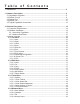
Table of Contents 1. Introduction...................................................................................................................5 2. Hardware Description .................................................................................................6 2.1 PageMatrix Controller ..............................................................................................6 2.2 Station Four-Wª .................................................................................................
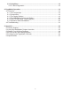
3.3.5. Help Menu........................................................................................................18 3.3.5.1 About Pagematrix ........................................................................................18 4. PageMatrix Operation ..................................................................................................19 4.1 Overview ..................................................................................................................19 4.1.
ENGLISH 1. Introduction Congratulations on wisely choosing the PageMatrixª system for your current and future paging projects. Used in conjunction with our highly-acclaimed MediaMatrix¨ digital audio system, PageMatrix provides an integrated and flexible approach to all serious paging applications. MediaMatrix serves as the central processing unit for an entire project, controlling the entire system from signal routing to managing the paging system.
2. Hardware Description 2.1 Pagematrix Controller The PageMatrix controller is the heart of the system. It is connected via an RS-232 serial port to the MediaMatrix frame running MediaMatrix and PageMatrix software. In fact, one PageMatrix controller can control up to four separate MediaMatrix systems (four control data ports are provided). In addition to the control ports, a single program port is available to receive data from the PageMatrix software.
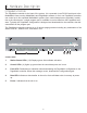
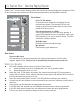
6 11 12 7 10 9 8 13 Rear Panel 6. Program Port (RS-232): Accepts PageMatrix software data from the host computerÕs serial port (Com 1 or Com 2). 7. Control Data Ports (4 RS-232 jacks): Allows connection and control of up to four MediaMatrix systems. 8. Station Inputs (16 RJ45 jacks): All stations are connected to one of the sixteen station inputs using standard CAT 5 cable. The cable carries audio from the station and control data to and from the station, as well as power for the station.
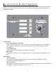
2.2. Station Four-W ™ Wall-Mount Paging Station Station Fourª-W is a four button wall mount station that includes a hand-held (5-pin) microphone with a push-to-talk switch. Each of the four zone presets are defined and programmed by the PageMatrix software. Front Panel Zone Preset buttons w/LEDs(4): Used to select any of the four zone presets. A green LED indicates the zone is available, while a red LED indicates it is in use by another station. The LED will blink to confirm the selection.
Station Four-W Operation ▲ ▲ ▲ ▲ ▲ ▲ ▲ ▲ LED color indicates status of each of the four Zone presets. ▲ Green indicates the zone is available and not in use by another station. ▲ Red indicates the zone is in use. When the microphone ÒTalkÓ button is pressed, the selected zone preset LED turns orange to confirm that it is active. Other stations connected to the system will indicate RED to confirm that this particular zone is in use. Press any Zone Preset button to select.
2.3. Station Four ™ Desktop Paging Station Station Fourª is a four button desktop station that includes an electret condenser microphone. Each of the four button zone presets are defined and programmed by the PageMatrix software. Front Panel Push To Talk button: Press and hold to enable the microphone for the selected zone preset. The selected LED will turn orange to denote active status while the other zone preset LEDs become red.
2.4. Station Ten ™ Desktop Paging Station Station Tenª is a ten button desktop station that includes an electret condenser microphone. Each of the ten zone presets are defined and programmed by the PageMatrix software. In addition, a 12 button Òtelephone styleÓ key pad and 20 x 2 LCD panel are provided for selection and indication of up to 99 ÒvirtualÓ zones.
Station Ten Operation ▲ ▲ ▲ ▲ ▲ ▲ ▲ ▲ ▲ ▲ ▲ ▲ LED color indicates status of each of the ten zone presets. ▲ Green indicates the zone is available and not in use by another station. ▲ Red indicates the zone is in use. When the Push To Talk button is pressed, the selected zone preset LED turns orange to confirm that it is active. Other stations connected to the system will indicate RED to confirm that the zone preset is in use. Press any Zone Preset button to select.
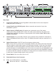
2.4. Typical PageMatrix Connection Up to 16 Stations of any combination CAT 5 STANDARD ÒData TypeÓ cable is used. However, there is voltage on the line. DO NOT CONNECT to computer networks.
3. PageMatrix Software Description 3.1. Computer Requirements Minimum: 486DX-100 or faster PC with Windows 3.1 / 95 / NT4 or later, 8-16Mb RAM and one available Com Port. 3.2. Software Installation Note: With MediaMatrix Mainframe systems shipped since 1999, the PageMatrix application is already installed. The instructions below only apply to systems prior to this time. The complete PageMatrix software system includes: 1. PageMatrix application (Floppy Disk 1) 2.
3.2.1. Launching PageMatrix Windows 95: 1. Under the Start menu, select Programs. 2. Find the PageMatrix directory and select it. 3. Locate PageMatrix , and select it. Windows 3.1: 1. Find the PageMatrix Program Group within the Program Manager 2. Doulbe click the group, then double click the PageMatrix Icon. Note: For systems that are not pre-loaded with PageMatrix, the MediaMatrix Program Launcher can be used. This is found under the MediaMatrix Device/Miscellaneous menu. See appendix 5.2. 3.2.2.
3.3. PAGEMATRIX APPLICATION MENU BAR OVERVIEW 3.3.1 File Menu New Selecting New opens a new configuration set to factory defaults. Open Brings up the standard file open dialog that allows you to open an existing file (*.pmx). Close Closes the active configuration. Save Save the current configuration and any edits you have made. Save As Brings up the standard file save dialog and allows you to rename the file before you save it. Print Not active at this time. Print Preview Not active at this time.
3.3.2. Edit Menu Undo Not active at this time Cut Not active at this time Copy Not active at this time Paste Not active at this time Insert Station Creates a new paging station that is available for editing. It is placed in the list before the currently selected station. Selecting this option opens the ÒNew Station PropertiesÓ dialog and allows the following edits: Station Name: Up to 16 characters. Number of buttons: 4 or 10.
3.3.3. Tools Menu/Options View Toolbar Show or hide the screen toolbar. View Status Bar Show or hide the status bar at the bottom of the window. View Station Addresses Displays the station address in front of the station name. Max Number of Zones Use this parameter to set the maximum number of zones used in your system. Communications Used to set the upload/download port. In addition to COM 1-4, an Offline Programming option is available when working remotely. 3.3.4.
4.0. Typical PageMatrix Operation 4.1. Overview 4.1.1. The components PageMatrix / MediaMatrix paging systems consist of five primary components: ▲ At least one PageMatrix paging station connected to the PageMatrix controller via the proper category five cabling ▲ PageMatrix controller with the appropriate configuration file loaded ▲ PageMatrix application software ▲ A MediaMatrix audio system with PASHA running ▲ A proper PASHA.ini file configured for the ÒView FileÓ compiled 4.1.2.
3: To interpret the proprietary control data from the paging stations and convert it to standard serial strings which can be forwarded to MediaMatrix. Microphone signals from the paging stations are not acted upon by the PageMatrix Controller, but are simply passed through the box as received. Any switching or routing is done within MediaMatrix. 4.1.4.
Basic OperationÐHere we go... 1. Find the appropriate .txt file for the device you wish to use. 2. Rename this file to pasha.ini and place in the Peavey directory (mediamatrix\views). Note: If you wish to keep the original pasha.ini file, just rename it. 3. Open MediaMatrix (if not already launched). 4. From the Device menu select ÒPagingÓ to view the available devices. 5. Select an existing device and wire it accordingly. 6. Test the routings and zones. Example: Suppose we want to use the 1632.pav file.
5. APPENDIX 5.1. Factory Support Peavey provides customer support and service direct from the factory. If you need further assistance or information, donÕt hesitate to call us. You can reach us 8 a.m. - 5 p.m. CST at (800) 543-2991 or (601) 483-5376. The address for correspondence/literature on current or new products is: Peavey Electronics Corp. ¥ MediaMatrix Support Group ¥ 711 A St.
5.2. Using the MediaMatrix Program Launcher The Program Launcher is found in the Device/Miscellaneous Menu. It is used to make it easy to open another Windows application while you are using MediaMatrix. You can label the Program Launcher block and include it in any window of a MediaMatrix design. The Program Launcher device can either launch another Windowsª application or switch to that application if it is already running.
5.3. Station 4-W Wiring Diagram Cat 5 Plug 4-Pin Connector 1 2 3 4 5 485+ 485 GND 24V+ GND Cat 5 Plug 3-Pin Connector 6 7 8 GND Line Out+ Line Out - CAT 5 87654321 8 7 2 6 1 3 5 4 NOTE: This is not a network connection.
5.4.
5.5. Configuring the PageMatrix Controller As mentioned previously, the PageMatrix controller supports up to sixteen paging stations simultaneously. In larger applications where multiple controllers are necessary, the various PageMatrix units must be configured for IDs beyond the default 1-16 setting. This is accomplished by changing the DIP switch settings inside the unit. 1. Remove top plate of the controller (six screws). 2.
5.6. Specifications PageMatrix Controller Power Requirements: Domestic: 120V AC~, 60 Hz, 50W Export: 100V AC~, 50/60 Hz, 50W 230V AC~, 50/60 Hz, 50W Category 5 cable length Maximum 1,000 ft Note: Standard Òdata typeÓ cable is used; however, there is voltage on the line. DO NOT connect to computer networks. Included Accessories: IEC Line Cord (4) 12 position Phoenix-type connectors (1) 3 position Phoenix-type connector Station Four-W Mounting Station 4-W Wallmount does not come with a back panel.
ESPA„OL 1. Introducción Lo felicitamos por su sabia elecci—n del sistema PageMatrixª para sus proyectos de intercomunicaci—n actuales y futuros. Utilizado en conjunto con nuestro aclamado sistema de audio digital MediaMatrix¨, el sistema PageMatrix provee un enfoque integrado y flexible para todas las aplicaciones de intercomunicaci—n profesionales.
▲ El controlador dispone de una entrada para el funcionamiento con alimentaci—n a distancia de +24 VCC. ▲ Se utilizan conectores tipo Phoenix para llevar la se–al de intercomunicaci—n de audio a las cajas distribuidoras BoB. ▲ El controlador sustenta hasta cuatro sistemas MediaMatrix. ▲ En el panel frontal del controlador hay 16 LED de estaci—n, que indican el estado de cada una de ellas. 2. Descripción del hardware 2.1 Controlador PageMatrix El controlador PageMatrix es el coraz—n del sistema.
6 11 12 7 10 9 8 13 Panel posterior 6. Puerto de programas (RS-232): Acepta los datos del software PageMatrix desde el puerto serie (Com 1 o Com 2) de la computadora central. 7. Puertos de datos (4 enchufes RS-232 hembra): Permiten la conexi—n y el control de hasta cuatro sistemas MediaMatrix. 8. Entradas de estaciones (16 enchufes RJ45 hembra): Todas las estaciones est‡n conectadas a una de las 16 entradas de estaci—n, mediante un cable CAT 5 est‡ndar.
2.2. Estación de intercomunicación de pared Station Four-W™ Es una estaci—n de intercomunicaci—n que incluye un micr—fono port‡til (de 5 terminales) con un pulsador para hablar. Cada una de las preprogramaciones de las cuatro zonas de intercomunicaci—n se define y programa con el software PageMatrix. Panel frontal Botones de zonas preprogramadas con LED indicadores (4): Utilizados para seleccionar cualquiera de las cuatro zonas preprogramadas.
Operación de la estación Station Four-W ▲ ▲ ▲ ▲ ▲ ▲ ▲ ▲ El color del LED indica el estado de cada una de las zonas preprogramadas. ▲ El color verde indica que la zona est‡ disponible y que no est‡ siendo utilizada por otra estaci—n. ▲ El color rojo indica que la zona est‡ en uso. Cuando se oprime el bot—n para hablar, el LED indicador de la zona preprogramada se ilumina de color naranja, para confirmar que est‡ activada.
2.3. Estación de intercomunicación de mesa Station Four™ Es una estaci—n de cuatro botones, que incluye un micr—fono de condensador de electreto. Cada una de las preprogramaciones de las cuatro zonas de intercomunicaci—n se define y programa con el software PageMatrix. Panel frontal Pulsador para hablar: MantŽngalo presionado para habilitar el micr—fono para la zona preprogramada seleccionada.
▲ ▲ ▲ ▲ Las zonas preprogramadas se pueden rotular en las casillas color blanco correspondientes. Si todos los LED indicadores destellan con luz roja al encender el sistema, significa que la estaci—n no ha sido programada. Si todos los LED indicadores destellan con luz verde al encender el sistema, significa que la estaci—n ha sido programada. La entrada de micr—fono auxiliar (panel posterior), siempre se encamina a la zona preprogramada 1. 2.4.
Volumen de micr—fono: Ajuste embutido de ganancia del micr—fono. Panel posterior Entrada de micr—fono auxiliar de 5 terminales: Se usa para conectar un micr—fono remoto con pulsador para hablar. Consulte el diagrama de cableado del ApŽndice 5.4. El micr—fono auxiliar se encamina autom‡ticamente a la zona preprogramada uno. Conector RJ45: Para conexi—n al controlador PageMatrix.
referimos a las asignaciones a los botones como Òzonas preprogramadasÓ, porque esas programaciones se establecen inicialmente y luego se cargan en el controlador PageMatrix donde se activan. Acerca de la prioridad Con el sistema PageMatrix, no hay par‡metros de prioridad inherentes a cada estaci—n f’sica. Cualquier micr—fono se puede utilizar en cualquier momento y el LED indicador ÒocupadoÓ identifica cuando una zona preprogramada es utilizada por otra estaci—n.
3. Descripción del software PageMatrix 3.1. Requisitos informáticos M’nimos: PC con procesador 486DX-100 o m‡s r‡pido, con Windows 3.1/95/NT4 o posterior, con 8 a16 MB de RAM y un puerto de comunicaciones disponible. 3.2. Instalación del software Nota: En los sistemas MediaMatrix Mainframe que se despachen a partir de 1999, la aplicaci—n PageMatrix ya estar‡ instalada. Las instrucciones que siguen se aplican s—lo a los sistemas anteriores a ese a–o.
B. Ejecute ÒA:\devices.exeÓ. C. ƒste es un archivo comprimido autoextraible, que solicita al usuario un directorio para instalar los archivos descomprimidos. Estos archivos DEBEN ESTAR en el directorio Devices (dispositivos) del directorio ra’z de su sistema MediaMatrix (c:\peavey\devices\standard\paging). Si su directorio ra’z es diferente al asignado por defecto, ingrese el directorio ra’z apropiado seguido por Òdevices\standard\pagingÓ. D.
Para incluir sus estaciones de hardware en la programaci—n, en el menœ Edit (edici—n,) utilice ÒInsert StationÓ (insertar estaci—n) o ÒAdd StationÓ (agregar estaci—n), segœn sea necesario. DespuŽs de configurar inicialmente la aplicaci—n PageMatrix, el diagrama de la izquierda muestra una columna con todas las estaciones de intercomunicaci—n conectadas. A la derecha hay una matriz con la lista de las zonas en la parte superior y columnas de botones numerados.
3.3.2. Menú Edit (edición) Undo (deshacer) Actualmente inactivo Cut (cortar) Actualmente inactivo Copy (copiar) Actualmente inactivo Paste (pegar) Actualmente inactivo Insert Station (insertar estaci—n) Crea una estaci—n de intercomunicaci—n nueva que queda disponible para edici—n. Se coloca en la lista precediendo a la estaci—n actualmente seleccionada.
3.3.3. Menœ de herramientas/opciones View Toolbar (ver barra de herramientas) Muestra u oculta la barra de herramientas en la pantalla. View Status Bar (ver barra de estado) Muestra u oculta la barra de estado en la parte inferior de la pantalla. View Station Addresses (ver las direcciones de las estaciones) Muestra la direcci—n de la estaci—n frente al nombre de la misma.
4.0. Operación típica del sistema PageMatrix 4.1. Reseña 4.1.1.
3: Interpretar los datos de control patentados de las estaciones de intercomunicaci—n y convertirlos en cadenas serie est‡ndar, que se pueden dirigir al sistema MediaMatrix. El controlador PageMatrix no actœa sobre las se–ales de las estaciones de intercomunicaci—n, s—lo pasan a travŽs de la caja como se reciben. Toda conmutaci—n o encaminamiento se efectœa dentro del sistema MediaMatrix. 4.1.4.
Operaci—n b‡sica - Aqu’ vamosÉ 1. Localice el archivo Ò.txtÓ correspondiente al dispositivo que desea utilizar. 2. Cambie el nombre del archivo por Òpasha.iniÓ e inst‡lelo en el directorio Peavey (mediamatrix\views). Nota: Si desea mantener el archivo Òpasha.iniÓ original, s—lo debe cambiarle el nombre. 3. Inicie el sistema MediaMatrix (si no se est‡ ejecutando ya). 4. Desde el menœ Device (dispositivo), seleccione ÒPagingÓ (intercomunicaci—n), para ver los dispositivos disponibles. 5.
A fin de proveerle el mejor apoyo tŽcnico, posiblemente sea necesario ver su archivo de visualizaci—n, de manera de poder diagnosticar su problema con precisi—n. Esto tambiŽn ayuda a agilizar su trabajo y a hacer m‡s eficiente su sistema. Por medio de Internet y del correo electr—nico, podemos ponerlo en servicio r‡pidamente. Tenga a bien dirigir su correo electr—nico con su archivo de visualizaci—n agregado a: George Douglas, National Sales Manager (Gerente Nacional de Ventas): george@peavey.
5.2. Utilización del MediaMatrix Program Launcher (iniciador de programas del sistema MediaMatrix) El Program Launcher (iniciador de programas), se encuentra en el menœ Device/Miscellaneous (dispositivos/varios). Se lo utiliza para simplificar la apertura de otra aplicaci—n Windows, mientras se est‡ usando el sistema MediaMatrix. Usted puede asignar nombre al bloque del Program Launcher e incluirlo en cualquier ventana de un dise–o MediaMatrix.
5.3. Station 4-W Wiring Diagram Cat 5 Plug 4-Pin Connector 1 2 3 4 5 485+ 485 GND 24V+ GND Cat 5 Plug 3-Pin Connector 6 7 8 GND Line Out+ Line Out - CAT 5 87654321 8 7 2 6 1 3 5 4 NOTE: This is not a network connection.
5.4.
5.5. Configuración del controlador del sistema PageMatrix Como se mencion— previamente, el controlador PageMatrix soporta simult‡neamente hasta 16 estaciones de intercomunicaci—n. En las aplicaciones m‡s grandes, en las que son necesarios varios controladores, las diferentes unidades del sistema PageMatrix se deben configurar con identidades m‡s all‡ de las 1 a 16 configuradas por defecto. Esto se logra modificando la configuraci—n de los interruptores DIP internos de la unidad. 1.
5.6. Especificaciones Controlador PageMatrix Requisitos de alimentaci—n: Modelos para los EE.UU.: 120 VCA~, 60 Hz, 50 W Modelos para exportaci—n: 100 VCA~, 50/60 Hz, 50 W 230 VCA~, 50/60 Hz, 50 W Longitud m‡xima del cable Categor’a 5: 305 m Nota: Se utiliza un cable Òtipo de datosÓ, pero sin embargo hay voltaje en la l’nea. NO LO CONECTE a redes de computaci—n. Estaci—n de pared Station Four-W (de 4 botones): La estaci—n de pared Station Four-W (de 4 botones) no viene con panel posterior.
INSTRUCCIONES DE SEGURIDAD IMPORTANTES ADVERTENCIA: Al utilizar productos elŽctricos se deben respetar las precauciones b‡sicas, que incluyen las siguientes: 1. Lea estas instrucciones. 2. Conserve estas instrucciones. 3. Preste atenci—n a todas las advertencias. 4. Respete todas las instrucciones. 5. No utilice este aparato cerca del agua. Por ejemplo, cerca o dentro de ba–eras, piscinas, lavaderos, s—tanos hœmedos, etc. 6. Limpie el aparato solamente con un trapo hœmedo. 7.
FRAN‚AIS 1. Introduction FŽlicitations pour avoir eu la sagesse de choisir le syst•me PageMatrixª pour vos projets de tŽlŽappel actuels et futurs. UtilisŽ en conjonction avec notre syst•me audio numŽrique MediaMatrix¨ universellement acclamŽ, le PageMatrix constitue une approche intŽgrŽe et souple pour toutes les applications de tŽlŽappel sŽrieuses. Le MediaMatrix sert de processeur central pour lÕensemble du projet, contr™lant la totalitŽ du syst•me, de lÕacheminement des signaux ˆ la gestion des appels.
▲ Quatre syst•mes MediaMatrix peuvent •tre raccordŽs au contr™leur. ▲ Le panneau avant du contr™leur est dotŽ de 16 DEL indiquant lÕŽtat des postes. 2. Description des composants matériels 2.1 Contrôleur PageMatrix Le contr™leur PageMatrix constitue le coeur du syst•me. Il est reliŽ par un port sŽrie RS-232 au ch‰ssis MediaMatrix sur lequel tournent les logiciels MediaMatrix et PageMatrix.
6 11 12 7 10 9 8 13 Panneau arri•re 6. Port de programmation (RS-232): accepte les donnŽes du logiciel PageMatrix transmises par le port sŽrie de lÕordinateur h™te (Com 1 ou Com 2). 7. Ports de donnŽes de contr™le (4 jacks RS-232): permettent de brancher et de contr™ler jusquÕˆ quatre syst•mes MediaMatrix. 8. EntrŽes de postes (16 jacks RJ45): tous les postes sont reliŽs ˆ lÕune de ces 16 entrŽes au moyen dÕun c‰ble CAT 5 standard.
2.2. Poste de téléappel à montage mural Station Four-W™ Le Station Fourª-W est un poste ˆ montage mural ˆ quatre touches comprenant un microphone ˆ main dotŽ dÕun alternat. Chacune des quatre prŽsŽlections de zone est dŽfinie et programmŽe par le logiciel PageMatrix. Panneau avant Touches de prŽsŽlection de zone avec DEL (4): Ces touches permettent dÕactiver les quatre zones prŽsŽlectionnŽes. Une DEL verte indique que la zone est libre alors quÕune DEL rouge signifie quÕelle est occupŽe par un autre poste.
Fonctionnement du poste Station Four-W ▲ La couleur des DEL indique lÕŽtat de chacune des zones prŽsŽlectionnŽes. ▲ La couleur verte indique que la zone nÕest pas utilisŽe par un autre poste et quÕelle est donc libre. ▲ La couleur rouge indique que la zone est occupŽe. ▲ Lorsque le bouton dÕalternat est enfoncŽ, la DEL de la zone sŽlectionnŽe devient orange, indiquant quÕelle est active. Les DEL des autres postes reliŽs au syst•me sont ROUGES pour confirmer que la zone en question est en usage.
2.3. Poste de téléappel de bureau Station Four™ Le Station Fourª est un poste de tŽlŽappel de bureau ˆ quatre touches comprenant un microphone ˆ condensateur Žlectret. Chacune des quatre prŽsŽlections de zone est dŽfinie et programmŽe par le logiciel PageMatrix. Panneau avant Alternat: Appuyez sur ce bouton et maintenez-le enfoncŽ pour activer le microphone de la zone sŽlectionnŽe.
▲ Si toutes les DEL clignotent en vert lors de la mise sous tension, cela signifie que le poste a ŽtŽ programmŽ. ▲ LÕentrŽe de microphone auxiliaire (panneau arri•re) est toujours acheminŽe ˆ la prŽsŽlection de zone 1. 2.4. Poste de téléappel de bureau Station Ten™ Le Station Tenª est un poste de tŽlŽappel de bureau ˆ dix touches comprenant un microphone ˆ condensateur Žlectret. Chacune des dix prŽsŽlections de zone est dŽfinie et programmŽe par le logiciel PageMatrix.
Panneau arri•re EntrŽe microphone auxiliaire ˆ 5 broches: DestinŽe au branchement dÕun microphone ˆ distance dotŽ dÕun alternat. Voir le schŽma de c‰blage ˆ lÕannexe 5.4. Le microphone auxiliaire est automatiquement acheminŽ ˆ la prŽsŽlection de zone 1. Connecteur RJ45: Pour le branchement du contr™leur PageMatrix. Fonctionnement du poste Station Ten ▲ La couleur des DEL indique lÕŽtat de chacune des zones prŽsŽlectionnŽes.
est occupŽe par un autre poste. Toutefois, des niveaux de prioritŽ complexes peuvent •tre configurŽs et intŽgrŽs au syst•me. 2.4. Typical PageMatrix Connection Up to 16 Stations of any combination CAT 5 STANDARD ÒData TypeÓ cable is used. However, there is voltage on the line. DO NOT CONNECT to computer networks.
3. Description du logiciel PageMatrix 3.1. Matériel requis Minimum: PC 486DX-100 ou plus rapide avec Windows version 3.1 / 95 / NT4 ou plus rŽcente, RAM de 8 ˆ 16 Mo et un port de communications libre. 3.2. Installation du logiciel Remarque: sur les syst•mes MediaMatrix Mainframe ˆ partir du mod•le 1999, lÕapplication MediaMatrix est dŽjˆ installŽe. Les instructions ci-dessous ne concernent que les mod•les antŽrieurs. Le syst•me logiciel PageMatrix complet inclut: 1.
rŽpertoire racine est diffŽrent de celui spŽcifiŽ en usine, entrez-le suivi de Òdevices\ standard\pagingÓ. D. Une fois le rŽpertoire confirmŽ, cliquez sur Unzip (dŽcompresser). E. Lorsque lÕinstallation est terminŽe, cliquez sur Close (fermer). 3.2.1. Lancement de PageMatrix Windows 95: 1. Dans le menu Start (DŽmarrer) sŽlectionnez Programs (Programmes). 2. SŽlectionnez le rŽpertoire PageMatrix. 3. SŽlectionnez PageMatrix. Windows 3.1: 1.
Noms des prŽsŽlections de zone avec le poste Station Ten Le poste Station Ten est dotŽ dÕun affichage 20 x 2 permettant de voir les prŽsŽlections de zone. Celles-ci sont nommŽes dans lÕapplication PageMatrix. LorsquÕun poste ˆ 10 touches est insŽrŽ (option Edit/Insert Station) lÕoption de texte appara”t en haut de lÕŽcran ACL. Il suffit alors de sŽlectionner une touche virtuelle, puis de mettre le titre par dŽfaut en surbrillance et de le modifier (maximum 16 caract•res). 3.3.
3.3.2. Menu Edit (Ždition) Undo (Annuler) Option non activŽe. Cut (DŽcouper) Option non activŽe. Copy (Copier) Option non activŽe. Paste (Coller) Option non activŽe. Insert Station (InsŽrer Poste) Cette option permet de crŽer un nouveau poste de tŽlŽappel pouvant •tre modifiŽ. Elle se trouve dans la liste avant le poste actuellement sŽlectionnŽ.
3.3.3. Menu Tools/Options (outils/options) View Toolbar (Afficher Barre DÕoutils) Permet dÕafficher ou de cacher la barre dÕoutils. View Status Bar (Afficher Barre DÕŽtat) Permet dÕafficher ou de cacher la barre dÕŽtat au bas de lÕŽcran. View Station Addresses (Afficher Adresses Des Postes) Permet dÕafficher lÕadresse dÕun poste, devant son nom. Max Number of Zones (Nombre Maximum De Zones) Ce param•tre dŽfinit le nombre maximum de zones utilisŽes avec le syst•me.
4.0. Fonctionnement de PageMatrix 4.1. Généralités 4.1.1. Composants Les syst•mes PageMatrix / MediaMatrix sont constituŽs de cinq composants principaux : ▲ Au moins un poste de tŽlŽappel PageMatrix reliŽ au contr™leur par un c‰ble de catŽgorie cinq adŽquat ▲ Un contr™leur PageMatrix dans lequel le fichier de configuration appropriŽ est chargŽ ▲ Le logiciel dÕapplication PageMatrix ▲ Un syst•me audio MediaMatrix pilotŽ par PASHA ▲ Un fichier PASHA.ini configurŽ pour le Òfichier de visualisationÓ Žtabli 4.
2: Il achemine les signaux analogiques de microphone des postes de tŽlŽappel aux entrŽes des bo”tes de distribution du contr™leur MediaMatrix. 3: Il analyse les donnŽes de contr™le de chaque poste de tŽlŽappel et les convertit en cha”nes de donnŽes standard pouvant •tre transmises au contr™leur MediaMatrix. Les signaux de microphone des postes de tŽlŽappel ne sont pas traitŽs par le contr™leur PageMatrix mais le traversent simplement tels quÕils sont re•us.
Utilisation de base Ð Tout dÕabord... 1. Trouvez le fichier .txt pour le syst•me que vous dŽsirez utiliser. 2. Donnez ce fichier le nom Pasha.ini et placez-le dans le rŽpertoire Peavey (mediamatrix\views). Remarque : Pour conserver le fichier pasha.ini existant, il suffit de le renommer. 3. Ouvrez MediaMatrix (sÕil nÕest pas dŽjˆ lancŽ). 4. Dans le menu Device (syst•mes), sŽlectionnez ÒPagingÓ (tŽlŽappel) pour voir les syst•mes disponibles. 5. Choisissez un syst•me existant et c‰blez-le correctement. 6.
5. Annexe 5.1. Assistance d’usine Peavey offre des services dÕassistance client•le et de rŽparations directement ˆ lÕusine. NÕhŽsitez pas ˆ nous appeler si vous dŽsirez notre aide ou des informations complŽmentaires. Vous pouvez nous joindre de 8 ˆ 17 heures HNC au (800) 543-2991 ou (601) 483-5376. Adressez toute correspondance ou demande de documentation sur les produits courants ou nouveaux ˆ lÕadresse suivante : Peavey Electronics Corp. ¥ MediaMatrix Support Group ¥ 711 A St.
5.2 Utilisation du lanceur de programme MediaMatrix Le lanceur de programme se trouve dans le menu Device/Miscellaneous (syst•me/divers). Il permet dÕouvrir facilement une autre application Windows pendant lÕutilisation de MediaMatrix. Le bloc de lanceur de programme peut •tre ŽtiquetŽ et inclus dans nÕimporte quelle fen•tre dÕun programme MediaMatrix. Le lanceur de programme peut soit lancer une autre application Windowª, soit passer ˆ cette application si elle est dŽjˆ ouverte.
5.3. Station 4-W Wiring Diagram Cat 5 Plug 4-Pin Connector 1 2 3 4 5 485+ 485 GND 24V+ GND Cat 5 Plug 3-Pin Connector 6 7 8 GND Line Out+ Line Out - CAT 5 87654321 8 7 2 6 1 3 5 4 NOTE: This is not a network connection.
5.4.
5.5. Configuration du contr™leur PageMatrix Comme il lÕa ŽtŽ mentionnŽ plus haut, le contr™leur PageMatrix peut commander jusquÕˆ 16 postes simultanŽment. Dans les applications plus Žtendues o• il est nŽcessaire dÕutiliser plusieurs contr™leurs, les codes dÕidentification des diffŽrentes unitŽs PageMatrix peuvent •tre configurŽs au-delˆ des rŽglages par dŽfaut 1 ˆ 16 au moyen des interrupteurs DIP se trouvant ˆ lÕintŽrieur de lÕappareil. 1. Retirez la plaque du dessus du contr™leur (six vis). 2.
5.6. Fiche technique Contr™leur PageMatrix Alimentation : ƒtats-Unis: 120 V c.a.~, 60 Hz, 50 W Exportation: 100 V c.a~, 50/60 Hz, 50 W 230 V c.a.~, 50/60 Hz, 50 W Longueur de c‰ble catŽgorie 5 1000 pieds (300 m) maximum Remarque: un c‰ble de ÒdonnŽesÓ standard est utilisŽ; toutefois une tension Žtant prŽsente sur la ligne. Veillez ˆ NE PAS le raccorder ˆ un rŽseau informatique.
NOTE IMPORTANTE CONCERNANT LA SECURITE ATTENTION: Lors de lÕutilisation de appareils Žlectriques, certaines mesures de sŽcuritŽ doivent •tre respectŽes: 1. Lisez toutes les instructions. 2. Conservez ces instructions. 3. Tenez compte de tous les avertissements. 4. Suivez prŽcisemment les instructions. 5. NÕutilisez pas lÕappareil ˆ proximitŽ de lÕeau. Par exemple prŽs dÕun bain, dÕune piscine, dÕun Žvier, ou dans un sous-sol humide. 6. Nettoyez avec un chiffon sec uniquement. 7.
DEUTSCH 1. Einleitung Wir beglŸckwŸnschen Sie zu Ihrer klugen Entscheidung, fŸr Ihren jetzigen und kŸnftigen Rufanlagen-Bedarf das PageMatrixª-System zu verwenden. Kombiniert mit unserem bewŠhrten, populŠren digitalen Audiosystem MediaMatrix¨ bildet PageMatrix eine integrierte, flexible Gesamtlšsung fŸr Rufanlagen mit professionellem Anspruch. MediaMatrix dient als Verarbeitungszentrale fŸr eine vollstŠndige Anlage und steuert alle AblŠufe Ð von der Signallenkung bis zur Rufanlagenverwaltung.
2. Beschreibung der Hardware 2.1 Der PageMatrix-Controller Der PageMatrix-Controller ist das HerzstŸck des Systems. Er wird Ÿber einen seriellen RS-232Anschlu§ am MediaMatrix-Computer angeschlossen, in dem MediaMatrix und das PageMatrixProgramm laufen. Ein PageMatrix-Controller kann bis zu vier separate MediaMatrix-Systeme steuern (er verfŸgt Ÿber vier SteuerungsanschlŸsse).
6 11 12 7 10 9 8 13 RŸckwand 6. Programmanschlu§ (RS-232): Dient zum Empfang der PageMatrix-Programmdaten vom seriellen Anschlu§ des Host-Computers (COM 1 oder COM 2). 7. Steuerungsdaten-AnschlŸsse (4 RS-232-Buchsen): Dienen zum Anschlu§ bzw. zur Steuerung von bis zu vier MediaMatrix-Systemen. 8. StationseingŠnge (16 RJ45-Buchsen): Jede Station wird mit einem CAT-5-Kabel an einem der sechzehn StationseingŠnge angeschlossen.
2.2. Rufstation Station Four-W™ zur Wandmontage Die Station Fourª-W ist eine fŸr die Wandmontage vorgesehene Station mit vier Tasten und einem Handmikrofon mit Drucktastenaktivierung. Die vier Zonenvoreinstellungen werden Ÿber die PageMatrix-Software definiert und programmiert. Frontplatte 4 Zonentasten mit Leuchtdioden: Dienen zum AnwŠhlen einer der vier voreingestellten Zonen. Eine grŸne Leuchtdiode zeigt an, da§ die betreffende Zone zugŠnglich ist.
Betrieb der Station Four-W ▲ ▲ ▲ ▲ ▲ ▲ ▲ ▲ Die Leuchtdiodenfarbe gibt den Status der jeweiligen Voreinstellzone wieder: ▲ GrŸn bedeutet, da§ die Zone frei ist, d.h. nicht von einer anderen Station gerufen wird. ▲ Rot bedeutet, da§ die Zone belegt ist. DrŸckt man auf die Sprechtaste des Mikrofons (ãTalkÒ), wird die gewŠhlte Zonentaste orange und bestŠtigt damit die Aktivierung.
2.3. Tisch-Rufstation Station Four™ Die Station Fourª ist eine Tischstation mit vier Tasten und einem Elektret-Kondensatormikrofon. Die Zonenvoreinstellungen der vier Tasten werden Ÿber die PageMatrix-Software definiert und programmiert. Frontplatte Tastenaktivierung: Zur Aktivierung des Mikrofons fŸr die gewŠhlte Zone die Taste gedrŸckt halten. Die entsprechende Leuchtdiode leuchtet orange auf, wŠhrend die Leuchtdioden der anderen Zonen rot leuchten.
2.4. Tisch-Rufstation Station Ten™ Die Station Tenª ist eine Tischstation mit zehn Tasten und einem Elektret-Kondensatormikrofon. Die zehn Zonenvoreinstellungen werden Ÿber die PageMatrix-Software definiert und programmiert. Au§erdem ist sie mit einer telefonŠhnlichen Tastatur mit 12 Tasten sowie einem 20 mal 2 Elementen gro§en LCD-Display ausgestattet, mit denen bis zu 99 ãvirtuelleÒ Zonen angewŠhlt und angezeigt werden kšnnen.
Betrieb der Station Ten ▲ ▲ ▲ ▲ ▲ ▲ ▲ ▲ ▲ ▲ ▲ ▲ Die Leuchtdiodenfarbe gibt den Status der jeweiligen Voreinstellzone wieder: ▲ GrŸn bedeutet, da§ die Zone frei ist, d.h. nicht von einer anderen Station gerufen wird. ▲ Rot bedeutet, da§ die Zone belegt ist. DrŸckt man auf die Sprechtaste, wird die gewŠhlte Zonentaste orange und bestŠtigt damit die Aktivierung. Andere am System angeschlossene Stationen zeigen die entsprechende Zonentaste ROT an und signalisieren damit, da§ die Zone belegt ist.
2.4. Typical PageMatrix Connection Up to 16 Stations of any combination CAT 5 STANDARD ÒData TypeÓ cable is used. However, there is voltage on the line. DO NOT CONNECT to computer networks.
3. Beschreibung der PageMatrix-Software 3.1. Computer-Anforderungen Mindestanforderungen: 486DX-100 oder schnellerer PC mit Windows 3.1 / 95 / NT4 oder spŠter, 8-16MB RAM und einem verfŸgbaren COM-Port. 3.2. Installieren der Software Hinweis: MediaMatrix-Mainframe-Systeme werden ab 1999 mit bereits installiertem PageMatrix-Programm ausgeliefert. Die nachfolgende Anleitung bezieht sich auf vor diesem Datum ausgelieferte Systeme. Die PageMatrix-Software besteht aus folgenden Einzelkomponenten: 1.
aufgefordert, in dem die entpackten Dateien abgelegt werden kšnnen. Diese Dateien M†SSEN im Verzeichnis ãDevicesÒ des MediaMatrix-Stammverzeichnisses gespeichert werden (c:\peavey\devices\standard\paging). Wenn das Stammverzeichnis nicht den vorgegebenen Namen hat, geben Sie bitte den entsprechenden Namen ein, gefolgt von ãdevices\standard\pagingÒ. D. BestŠtigen Sie das Verzeichnis, und klicken Sie auf ãUnzipÒ. E. Klicken Sie nach Abschlu§ der Installation auf ãCloseÒ. 3.2.1.
links auf dem Bildschirm eine Spalte zu sehen, in der alle angeschlossenen Rufstationen aufgelistet sind. Rechts oben befindet sich eine Matrix-Liste der Zonen, darunter die Spalten mit den durchnumerierten Tasten. WŠhlen Sie die Station aus, die Sie zuerst programmieren mšchten, und aktivieren Sie dann mit der Maus Zonen fŸr jede Ruftaste. Wenn Sie fertig sind, laden Sie die Konfiguration in den PageMatrix-Controller (MenŸ ãFileÒ). Nun sind die Tasten an den Rufstationen programmiert und einsatzbereit.
3.3.2. MenŸ ãEditÒ (Bearbeiten) Undo (RŸckgŠngig) Derzeit noch nicht benutzbar. Cut (Ausschneiden) Derzeit noch nicht benutzbar. Copy (Kopieren) Derzeit noch nicht benutzbar. Paste (EinfŸgen) Derzeit noch nicht benutzbar. Insert Station (Station einfŸgen) Dient zum Erstellen einer neuen Rufstation, die dann bearbeitet werden kann. Sie erscheint auf der Liste vor der derzeit gewŠhlten Station.
3.3.3. MenŸ ãTools/OptionsÒ View Toolbar (Symbolleiste einblenden/ausblenden) Bestimmt, ob die Symbolleiste angezeigt wird oder nicht. View Status Bar (Statusleiste einblenden/ausblenden) Bestimmt, ob die Statusleiste am unteren Rand des Fensters angezeigt wird oder nicht. View Station Addresses (Stationsadressen anzeigen) Vor jedem Stationsnamen wird die Stationsadresse angezeigt. Max Number of Zones (max. Anzahl von Zonen) Mit diesem Parameter wird die maximale Anzahl der Zonen in dem System festgelegt.
4.0. Das Funktionsschema von PageMatrix 4.1. Überblick 4.1.1. Die Komponenten PageMatrix/MediaMatrix-Rufsysteme bestehen aus fŸnf Hauptkomponenten: ▲ Mindestens einer PageMatrix-Rufstation, die mit den richtigen CAT-5-Kabeln am PageMatrix-Cotroller angeschlossen ist. ▲ Dem PageMatrix-Controller, in den die benštigte Konfigurationsdatei geladen wurde. ▲ Der PageMatrix-Software ▲ Einem MediaMatrix-Audiosystem, in dem PASHA lŠuft. ▲ Einer Datei namens PASHA.
3: Die Interpretation der proprietŠren, von den Rufstationen gesendeten Steuerungsdaten und deren Umwandlung in serielle Standardstrings, die an MediaMatrix weitergeleitet werden kšnnen. Der PageMatrix-Controller verarbeitet die Mikrofonsignale von den Rufstationen in keiner Weise, sondern leitet sie sofort und unverŠndert weiter. Alle Schalt- und LeitvorgŠnge finden innerhalb von MediaMatrix statt. 4.1.4.
Inbetriebnahme Ð So wirdÕs gemachtÉ 1. Suchen Sie die *.txt-Datei zu der Einheit, die Sie benutzen mšchten. 2. Benennen Sie diese Datei in ãpasha.iniÒ um, und speichern Sie sie im PeaveyVerzeichnis ãmediamatrix\viewsÒ. Hinweis: Wenn Sie die ursprŸngliche ãpasha.iniÒ-Datei behalten mšchten, geben Sie ihr einfach einen anderen Namen. 3. …ffnen Sie MediaMatrix (sofern nicht bereits geschehen). 4. Um die verfŸgbaren Einheiten einsehen zu kšnnen, wŠhlen Sie im MenŸ ãDeviceÒ die Option ãPagingÒ. 5.
5. Anhang 5.1. Werkseitiger Service Peavey bietet direkten Werkskundendienst an. Sollten Sie weitere Hilfe oder zusŠtzliche Informationen benštigen, rufen Sie uns bitte an. Sie erreichen uns von 8.00 bis 17.00 CST (= sieben Stunden frŸher als MEZ) unter 001 601 483 5376. Die Anschrift fŸr alle Korrespondenzen sowie zum Anfordern von LektŸre zu aktuellen und neuen Produkten lautet: Peavey Electronics Corp. ¥ MediaMatrix Support Group ¥ 711 A St.
5.2. Der MediaMatrix Program Launcher Der Program Launcher (Programmstarter) ist im MenŸ ãDevice/MiscellaneousÒ zu finden. Er erleichtert das …ffnen anderer Windows-Programme, wŠhrend mit MediaMatrix gearbeitet wird. Den Program Launcher-Block kšnnen Sie beschriften und in jedes beliebige Fenster eines MediaMatrixDesigns aufnehmen. Der Program Launcher startet entweder ein anderes Windowsª-Programm, oder er schaltet zu diesem Programm um, wenn es bereits lŠuft.
5.3. Station 4-W Wiring Diagram Cat 5 Plug 4-Pin Connector 1 2 3 4 5 485+ 485 GND 24V+ GND Cat 5 Plug 3-Pin Connector 6 7 8 GND Line Out+ Line Out - CAT 5 87654321 8 7 2 6 1 3 5 4 NOTE: This is not a network connection.
5.4.
5.5. Konfigurieren des PageMatrix-Controllers Wie bereits erwŠhnt, unterstŸtzt der PageMatrix-Controller bis zu sechzehn Rufstationen gleichzeitig. Bei umfangreichen Systemen mit mehreren Controllern mŸssen die einzelnen PageMatrix-Einheiten Kennungen (IDÕs) erhalten, die Ÿber die Standardeinstellung von 1 bis 16 hinausgehen. Dies geschieht durch €ndern der DIP-Schalterstellungen in der jeweiligen Einheit. 1. 2. 3. 4. Obere Deckplatte des Controllers abnehmen (sechs Schrauben).
5.6. Technische Daten PageMatrix-Controller Anschlu§werte USA: 120 V~, 60 Hz, 50 W Export: 100 V~, 50/60 Hz, 50 W 230 V~, 50/60 Hz, 50 W Hinweis: Es wird Standard-ãDatenkabel" verwendet; dieses steht jedoch unter Spannung! Kabel NICHT an Computernetzwerken anschlie§en! Zubehšr im Lieferumfang: IEC-Netzkabel 4 Phoenix-Stecker mit 12 Positionen 1 Phoenix-Stecker mit 3 Positionen Montage der Station Four-W Die Station 4-W zur Wandmontage wird ohne RŸckwand ausgeliefert.
WICHTIGE SICHERHEITSRICHTLINIEN WARNUNG: Beim Einsatz elektrischer GerŠte sollten stets nachfolgend genannte grundlegende Sicherheitsrichtlinien beachtet werden: 1. Lesen Sie diese Richtlinien. 2. Bewahren Sie diese Richtlinien stehts griffbereit auf. 3. Beachten Sie sŠmtliche Richtlinien. 4. Befolgen Sie alle Anweisungen. 5. Benutzen Sie das GerŠt nicht in unmittelbarer WassernŠhe (z. B. Badewanne, Waschbecken, Swimming-Pool, etc.). 6. Nur mit einem feuchten oder klammen Tuch reinigen. 7.
NOTES: 100
NOTES: 101
IMPORTANT SAFETY INSTRUCTIONS WARNING: When using electric products, basic cautions should always be followed, including the following: 1. Read these instructions. 2. Keep these instructions. 3. Heed all warnings. 4. Follow all instructions. 5. Do not use this apparatus near water. For example, near or in a bathtub, swimming pool, sink, wet basement, etc. 6. Clean only with a damp cloth. 7. Do not block any of the ventilation openings. Install in accordance with manufacturerÕs instructions.
PEAVEY ELECTRONICS CORPORATION LIMITED WARRANTY Effective Date: July 1, 1998 What This Warranty Covers Your Peavey Warranty covers defects in material and workmanship in Peavey products purchased and serviced in the U.S.A. and Canada.
Features and specifications subject to change without notice. Peavey Electronics Corporations ¥ 711 A Street ¥ Meridian, MS 39301 ¥ U.S.A. (601) 483-5367 ¥ Fax (601) 486-1678 ¥ www.peavey.com ©1999 80304504 Printed in U.S.A.