
User Manual


4. Pulse Width Trigger
Pulse trigger occurs according to the width of pulse. The abnormal signals can be detected through setting up
the pulse width condition.
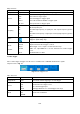
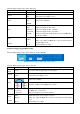
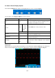
The Pulse Width Trigger Menu is shown as Fig. 33.
Fig. 33 Pulse Width Trigger menu
Pulse Width Trigger menu list
MENU SETTING INSTRUCTION
Single Mode Pulse
Set vertical channel trigger type as pulse trigger.
Source
CH1
CH2
Select CH1 as the trigger source.
Select CH2 as the trigger source.
Coupling
AC
DC
HF
LF
Not allow DC portion to pass.
Allow all portion pass.
Not allow high frequency of signal pass and only low
frequency portion pass.
Not allow low frequency of signal pass and only high
frequency portion pass
when
Polarity
Choose the polarity
Select pulse width condition and adjust the M knob to set
time.
Mode
Holdoff
Auto
Normal
Single
Holdoff
Reset
Acquire waveform even no trigger occurred
Acquire waveform when trigger occurred
When trigger occurs, acquire one waveform then stop
100ns~10s, adjust M knob to set time interval before
another trigger occur.
Set Holdoff time as 100ns
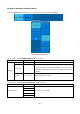
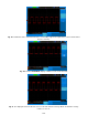
5. Alternate trigger
Trigger signal comes from two vertical channels when alternate trigger is on. This mode is used to observe two
unrelated signals. You can choose different trigger modes for different channels. The options are as follows:
edge, video, pulse or slope.
-122-