
User Manual

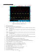

16. The frequency of the trigger signal of CH2.
17. It indicates the current function menu.
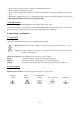
18/19. It shows the selected trigger type:
Rising edge triggering
Falling edge triggering
Video line synchronous triggering
Video field synchronous triggering
The reading shows the trigger level value of the corresponding channel.
20. The reading shows the window time base value.
21. The reading shows the setting of main time base.
22. The readings show current sample rate and the record length.
23. It indicates the measured type and value of the corresponding channel. “F” means frequency, “T”
means cycle, “V” means the average value, “Vp” the peak-peak value, “Vk” the root-mean-square
value, “Ma” the maximum amplitude value, “Mi” the minimum amplitude value, “Vt” the Voltage value
of the waveform’s flat top value, “Vb” the Voltage value of the waveform’s flat base, “Va” the
amplitude value, “Os” the overshoot value, “Ps” the Preshoot value, “RT” the rise time value, “FT” the
fall time value, “PW” the +width value, “NW” the -Width value, “+D” the +Duty value, “-D” the -Duty
value, “PD” the Delay A
B value and “ND” the Delay A B value.
24. The readings indicate the corresponding Voltage Division and the Zero Point positions of the
channels.
The icon shows the coupling mode of the channel.
“—” indicates the direct current coupling
“~” indicates the AC coupling
“ ” indicates GND coupling
25. It is cursor measure window, showing the absolute values and the readings of the two cursors.
26. The yellow pointer shows the grounding datum point (zero point position) of the waveform of the CH2
channel. If the pointer is not displayed, it shows that this channel is not opened.
27. The red pointer indicates the grounding datum point (zero point position) of the waveform of the CH1
channel. If the pointer is not displayed, it shows that the channel is not opened.
Note:
If a M -symbol appears in the menu, it indicates you can turn the M knob to set the current menu.
4. How to implement the General Inspection
After you get a new oscilloscope, it is recommended that you should make a check on the instrument
according to the following steps:
1. Check whether there is any damage caused by transportation.
If it is found that the packaging carton or the foamed plastic protection cushion has suffered serious
damage, do not throw it away first till the complete device and its accessories succeed in the electrical
and mechanical property tests.
-99-