
User Manual


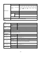


Measurement
Cursor
△V and △T between cursors
Automatic measurement
functions
Vpp, Vmax, Vmin, Vtop, Vbase, Vamp, Vavg, Vrms,
Overshoot, Preshoot, Freq, Period, Rise Time,Fall Time,
DelayA→B , DelayA→B , +Width, -Width, +Duty,
-Duty
Waveform Math
+, - , *, /, FFT
Waveform storage
4 waveforms
Lissajou’s
figure
Bandwidth
Full bandwidth
Phase
difference
± 3°
Frequency ( typical)
1 kHz square wave
Communication
port
1x USB 2.0 (Device), 1x USB for file storage (Host)
* Single channel is when only one input channel is available.
Trigger:
Trigger level range
Internal
± 6 div from the screen center
EXT
± 600 mV
EXT/5
± 3 V
Trigger level
Accuracy (typical)
Internal
± 0.3 div
EXT
± (40 mV + 6 % of Set Value)
EXT/5
± (200 mV +6 % of Set Value)
Trigger displacement
Pre-trigger: 655 div. Post-trigger: 4 div
Trigger Holdoff range
100 ns ~ 10 s
50% level
setting(typical)
Input signal frequency ≥ 50 Hz
Edge trigger
slope
Rising, Falling
Sensitivity
0.3 div
Pulse trigger
Trigger condition
Positive pulse: >, <, =
Negative pulse: >, <, =
Pulse Width range
24 ns ~ 10s
Video Trigger
Modulation
Supports standard NTSC, PAL and SECAM broadcast systems
Line number range
1-525 (NTSC) and 1-625 (PAL/SECAM)
Slope Trigger
Trigger condition
Positive pulse: >, <, =
negative pulse: >, <, =
Time setting
24 ns ~ 10 s
Alternate Trigger
Trigger on CH1
Edge, Pulse, Video, Slope
Trigger on CH2
Edge, Pulse, Video, Slope
-228-