
User Manual


The description of the Channel Menu is shown as the following list:
Function Menu
Setting
Description
Coupling
AC
DC
GROUND
Block the DC component in the input signal.
Unblock the AC and DC components in the input signal.
The Input signal is interrupted.
Band Limit
OFF 100 MHz
ON 20 MHz
Get full bandwidth.
Limits the channel bandwidth to 20MHz to reduce display noise.
Channel
OFF
ON
Close the measurement channel.
Open the measuring channel.
Probe
1X
10X
100X
1000X
Choose one according to the probe attenuation factor to make the
vertical scale reading accurate.
Inverted
OFF
ON
The wave form is displayed normally.
Initiate the wave form inverted function.
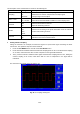
1. Setting Channel Coupling
Taking the Channel 1 for example, the measured signal is a square wave signal containing the direct
current bias. The operation steps are shown as below:
1. Press the CH1 MENU button and call out the CH1 SETUP menu.
2. Press the F1 menu selection button and select the Coupling item as “AC” to set the channel coupling
as ac mode, under which the direct current component in the signal will be blocked.
3. Then, press the F1 menu selection button again and select the Coupling item as “DC”, setting the
channel coupling as dc mode, under which both dc and ac components in the signal will be
unblocked.
The wave forms are shown as Fig. 20 and Fig. 21.
-130-
Fig. 20 AC Coupling Oscillogram
-140-