
User Manual


9. Introduction to the Vertical System
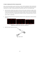
Shown as Fig. 8, there are a series of buttons and knobs in VERTICAL CONTROLS. The following practices
will gradually direct you to be familiar with the using of the vertical setting.
Fig. 8 Vertical Control Zone
1. Use the button “VERTICAL POSITION” knob to show the signal in the center of the waveform
window. The “VERTICAL POSITION” knob functions the regulating of the vertical display
position of the signal. Thus, when the “VERTICAL POSITION” knob is rotated, the pointer of the
earth datum point of the channel is directed to move up and down following the wave form.
Measuring Skill
If the channel is under the DC coupling mode, you can rapidly measure the DC component of the signal
through the observation of the difference between the wave form and the signal ground.
If the channel is under the AC mode, the DC component will be removed by filtration. This mode helps
you display the AC component of the signal with a higher sensitivity.
2. Change the Vertical Setting and Observe the Consequent State Information Change.
With the information displayed in the status bar at the bottom of the waveform window, you can determine
any changes in the channel vertical scale factor.
* Rotate the vertical “VOLTS/DIV” knob and change the “Vertical Scale Factor (Voltage Division)”, it can
be found that the scale factor of the channel corresponding to the status bar has been changed
accordingly.
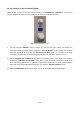
* Press buttons of “CH1 MENU”, “CH2 MENU” and “MATH MENU”, the operation menu, symbols, wave
forms and scale factor status information of the corresponding channel will be displayed in the screen.
-129-