
User Manual
- 35 -
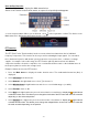
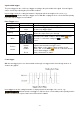
Trigger Brief description
The single, logic and bus trigger menus are described below:
Edge trigger: Occurs when the trigger input passes through a specific voltage level with the specified slope.
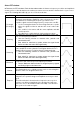
Video Trigger: Trigger on fields or lines for a standard video signal.
Slope Trigger: The oscilloscope starts triggering according to the rate of rise or fall of the signal.
Pulse Trigger: Finds pulses with specific widths.
Runt Trigger: Trigger pulses that pass through one trigger level but not through the other trigger level.
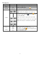
Windows trigger: Gives a high trigger level and low trigger level. The oscilloscope
triggers when the input signal passes through the high or low trigger level.
Timeout Trigger: The oscilloscope triggers when the time interval from the time of the
rising edge (or falling edge) by the trigger level when the adjacent falling edge (or rising edge) by the trigger
level is greater than the set timeout time.
Nth Edge Trigger: The oscilloscope triggers on the Nth edge that appears on the specified idle time.
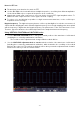
Detailed trigger description
RS232 Trigger: RS232 is a serial communication mode used in data transfer between PCs or between PC
and terminal.
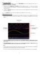
I2C trigger
The I2C serial bus consists of SCL and SDA. The transmission rate is determined by SCL and the
transmission data is determined by SDA.
SPI trigger
Trigger the specified data when the timeout is met. When using SPI
Trigger, you must specify the SCL and SDA data sources.
CAN bus trigger
CAN (Controller Area Network) is a serial communication protocol of the international ISO standardisation.