Multi-Function 802.11b+g Wireless Router 802.11g/802.
Table of Contents INTRODUCTION..................................................................................................................... 2 Wireless Router Features ................................................................................................. 2 Package Contents .............................................................................................................. 4 Physical Details...........................................................................................
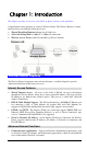
Chapter 1: Introduction This Chapter provides an overview of the Wireless Router's features and capabilities. Congratulations on the purchase of your new Wireless Router. The Wireless Router is a multifunction device providing the following services: • • • Shared Broadband Internet Access for all LAN users. 4-Port Switching Hub for 10BaseT or 100BaseT connections. Wireless Access Point for 802.11b and 802.11g Wireless Stations.
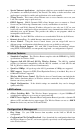
Introduction • Special Internet Applications. Applications which use non-standard connections or port numbers are normally blocked by the Firewall. The ability to define and allow such applications is provided, to enable such applications to be used normally. • Virtual Servers. This feature allows Internet users to access Internet servers on your LAN. The required setup is quick and easy. • DDNS Support.
• Remote Management. The Wireless Router can be managed from any PC on your LAN. And, if the Internet connection exists, it can also (optionally) be configured via the Internet. • Network Diagnostics. You can use the Wireless Router to perform a Ping or DNS lookup. • UPnP Support. UPnP (Universal Plug and Play) allows automatic discovery and configuration of the Wireless Router. UPnP is by supported by Windows ME, XP, or later. Security Features • Password - protected Configuration.
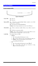
Introduction Physical Details Front-mounted LEDs Figure 1: Front Panel Power LED On - Power on. Off - No power. Internet LED On - Connection to the Broadband Modem attached to the WAN (Internet) port is established. Off - No connection to the Broadband Modem. Flashing - Data is being transmitted or received via the WAN port. WLAN LED On - Wireless connection available; Wireless Access Point is ready for use. Off - No Wireless connection available.
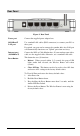
Rear Panel Figure 2: Rear Panel Power port Connect the supplied power adapter here. 10/100BaseT LAN port Use standard LAN cables (RJ45 connectors) to connect your PCs to these ports. If required, any port can be connected to another hub. Any LAN port will automatically function as an "Uplink" port when necessary. Internet port (10/100BaseT) Connect the DSL or Cable Modem here. If your modem came with a cable, use the supplied cable. Otherwise, use a standard LAN cable.
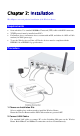
Chapter 2: Installation This Chapter covers the physical installation of the Wireless Router. Requirements • Network cables. Use standard 10/100BaseT network (UTP) cables with RJ45 connectors. • TCP/IP protocol must be installed on all PCs. • For Internet Access, an Internet Access account with an ISP, and either of a DSL or Cable modem (for WAN port usage) • To use the Wireless Access Point, all Wireless devices must be compliant with the IEEE802.11b or IEEE802.11g specifications. Procedure 1.
If required, connect any port to a normal port on another Hub, using a standard LAN cable. Any LAN port on the Wireless Router will automatically function as an "Uplink" port when required. 3. Connect WAN Cable Connect the DSL or Cable modem to the WAN port on the Wireless Router. Use the cable supplied with your DSL/Cable modem. If no cable was supplied, use a standard cable. 4. Power Up • Power on the Cable or DSL modem. • Connect the supplied power adapter to the Wireless Router and power up.
Chapter 3: Setup This Chapter provides Setup details of the Wireless Router. Overview This chapter describes the setup procedure for: • Internet Access • LAN configuration • Wireless setup • Assigning a Password to protect the configuration data. PCs on your local LAN may also require configuration. For details, see Chapter 4 - PC Configuration. Other configuration may also be required, depending on which features and functions of the Wireless Router you wish to use.
• Double - click the icon for the Wireless Router (either on the Desktop, or in My Network Places) to start the configuration. Refer to the following section Setup Wizard for details of the initial configuration process. Using your Web Browser To establish a connection from your PC to the Wireless Router: 1. After installing the Wireless Router in your LAN, start your PC. If your PC is already running, restart it. 2. Start your WEB browser. 3.
Setup Wizard The Setup Wizard provides brief and basic configuration of this device, you may enter each screen to change the default settings. For more detailed settings, you may refer to the “Configuration via Web” section. 1. View the listed configuration items and click Next to continue. 2. Configure Time Zone and NTP server by enabling NTP client update. Click Next to continue. 3.
5. Configure the parameters for wireless LAN clients. Check the Disable Access Point to disable the settings of this screen. Click Next to continue. 6. To manage your wireless network security by selecting the encryption type (None, WEP and WPA (TKIP)) from the pull-down menu. Click Finish to exit Set Wizard screen. Common Connection Types Cable Modems Type Dynamic IP Address Details Your IP Address is allocated automatically, when you connect to you ISP.
DSL Modems Type Details ISP Data required Dynamic IP Address Your IP Address is allocated automatically, when you connect to you ISP. None. Static (Fixed) IP Address Your ISP allocates a permanent IP Address to you. IP Address allocated to you. PPPoE You connect to the ISP only when required. The IP address is usually allocated automatically. User name and password. PPTP Mainly used in Europe. • PPTP Server IP Address. You connect to the ISP only when required.
IP Address Default: 192.168.1.254 (this is the local address of this Router) Subnet Mask Default: 255.255.255.0 DHCP Disable: Select to disable this Router to distribute IP Addresses (Disabled) Server: Select to enable this Router to distribute IP Addresses (DHCP Server). And the following field will be activated for you to enter the starting IP Address DHCP Client Range The starting address of this local IP network address pool. The pool is a piece of continuous IP address segment.
Status Internet Shows the internet connection status LAN Shows the Local area network information System Briefly shows the device name and firmware information Connection Details Click to show more details of the internet connection System Data Click to show the detailed information of the system Refresh Screen Click to refresh all the data Wireless Basic Settings Disable Access Point Check to disable the AP function.
2.4GHz (B): 802.11b supported rate only. 2.4GHz (G): 802.11g supported rate only. 2.4GHz (B+G): 802.11b supported rate and 802.11g supported rate. The default is 2.4GHz (B+G) mode. Network Type Infrastructure: If set to Client (Infrastructure) mode, this device can work like a wireless station when it’s connected to a computer so that the computer can send packets from wired end to wireless interface.
share a secret key. Auto: Select Auto Switch for the adapter to automatically select the appropriate Preamble Type A preamble is a signal used in wireless environment to synchronize the transmitting timing including Synchronization and Start frame delimiter. (Note: If you want to change the Preamble type into Long or Short, please check the setting of AP.) Broadcast SSID Enable: This wireless AP will broadcast its SSID to stations. Disable: This wireless AP will not broadcast its SSID to stations.
Encryption: WEP If WEP is selected, users will have to Set WEP keys either manually, or select to Use 802.1x Authentication to make the RADIUS server to issue the WEP key dynamically. SET WEP KEY Click the Set WEP Keys will prompt you a window to set 64bit or 128bit Encryption. Select HEX if you are using hexadecimal numbers (0-9, or A-F). Select ASCII if you are using ASCII characters (case-sensitive).
Authentication standardized through 802.11i/WPA2 are: pre-authentication, which enables secure fast roaming without noticeable signal latency. Preauthentication provides a way to establish a PMK security association before a client associates. The advantage is that the client reduces the time that it's disconnected to the network. Authentication RADIUS Port: Enter the RADIUS Server’s port number provided by Server your ISP. The default is 1812.
Reset Click Reset to restore to default values. Access Control Enable Access Control Select to enable Access Control function. Select Services to Block This lists all defined Services. Select the Services you wish to block. Port Range For TCP and UDP Services, enter the beginning of the range of port numbers used by the service. If the service uses a single port number, enter it in both the start and finish fields.
Dynamic DNS Enable DDNS Select to enable DDNS function. This free service is very useful when combined with the Virtual Server feature. It allows Internet users to connect to your Virtual Servers using a URL, rather than an IP Address. This also solves the problem of having a dynamic IP address. With a dynamic IP address, your IP address may change whenever you connect, which makes it difficult to connect to you. Service Provider • Select the desired DDNS Service Provider from the list.
DMZ Enable DMZ If the DMZ Host Function is enabled, it means that you set up DMZ host at a particular computer to be exposed to the Internet so that some applications/software, especially Internet / online game can have two-way connections. DMZ Host IP Address Enter the IP address of a particular host in your LAN which will receive all the packets originally going to the WAN port/Public IP address above. Note: You need to give your LAN PC clients a fixed/static IP address for DMZ to work properly.
numbers or by names. Maximum 24 Server entries are allowed and each port number can only be assigned to one IP address. Local IP Address Enter the Local Server’s IP address. Protocol Select the protocol (TCP, UDP or Both) used to the remote system or service. Port Range For TCP and UDP Services, enter the beginning of the range of port numbers used by the service. If the service uses a single port number, enter it in both the start and finish fields.
Range Once the trigger port is detected, the incoming packets are allowed to pass the firewall to these already specified Incoming Ports. Trigger Type Click the down arrow b to select the trigger type (TCP or UDP) Trigger Start Port Enter a port number as the starting outbound port for the special application defined in the preceding field. Trigger Finish Port Enter a port number as the ending outbound port for the special application defined in the preceding field.
Enable L2TP pass through on VPN conenction Save After completing the settings on this page, click Save to save the settings. Reset Click Reset to restore to default values. Ping This screen allows you to perform a "Ping". The response messages that will appear below can be useful in diagnosing network problems. IP Address/ Host Enter the IP address or domain name that you want to ping. name Run Click to start pinging. Reset Click to clear the current IP address /Host name.
Enable DoS Prevention Check to enable the DoS prevention function. Select the item listed to enable. Enable Source IP Set the threshold for the frequency of packets that are allowed to pass Blocking Block through. The default value is 50 packets per seconds. You can adjust the value according to your need. It is recommended that you set a practical time (sec) number so that your network performance won’t be hampered. Selct All Click to selct all listed items. Clear All Click to clear all listed items.
Enable web Server Access via WAN Check to enable the function. Port number Save Click to save the current settings. Reset Click to clear the current settings. Config File This feature allows you to download the current settings from the Wireless Router, and save them to a file on your PC. You can restore a previously downloaded configuration file to the Wireless Router, by uploading it to the Wireless Router.
This will delete ALL of the existing settings. Log The Logs record various types of activity on the Wireless Router. This data is useful for troubleshooting, but enabling all logs will generate a large amount of data and adversely affect performance. Enable Log Click to enable log function. Enable Remote Log Click to enable the remote log function. The log record will be saved into a remote server.
Enable IP Filtering Check to enable the IP filtering function. Local IP Address Enter the client IP address. Protocol Select the protocol (TCP, UDP or Both) used to the remote system or service. Description You may key in a description for the local IP address Current Filter Table Shows the current filter information. Save After completing the settings on this page, click Save to save the settings. Reset Click Reset to restore to default values.
Statistics Refresh Click to refresh the statistics table. Time Zone Setting Current Time Enter the current time of this wireless router. Enable NTP client update Check to enable NTP (Network Time Protocol Server) client update function. Time Zone Select Select the time zone from the pull-down menu. NTP server You may choose to select NTP server from the pull-down menu or enter an IP address of a specific server. Save After completing the settings on this page, click Save to save the settings.
Upgrade Firmware Browse Click the Browse button, find and open the firmware file (the browser will display to correct file path). Start Upgrade Click the Start Upgrade button to perform Reset Click Reset to restore to default values. Navigation & Data Input • Use the menu bar on the left of the screen, and the "Back" button on your Browser, for navigation. • Changing to another screen without clicking "Save" does NOT save any changes you may have made.
Chapter 4: PC Configuration Overview For each PC, the following may need to be configured: • TCP/IP network settings • Internet Access configuration • Wireless configuration Windows Clients This section describes how to configure Windows clients for Internet access via the Wireless Router. The first step is to check the PC's TCP/IP settings. The Wireless Router uses the TCP/IP network protocol for all functions, so it is essential that the TCP/IP protocol be installed and configured on each PC.
Checking TCP/IP Settings - Windows 98/ME: 1. Select Control Panel - Network. You should see a screen like the following: 2. 3. Select the TCP/IP protocol for your network card. Click on the Properties button. You should then see a screen like the following. Ensure your TCP/IP settings are correct, as follows: Using DHCP To use DHCP, select the radio button Obtain an IP Address automatically. This is the default Windows setting. Using this is recommended.
• On the DNS Configuration tab, ensure Enable DNS is selected. If the DNS Server Search Order list is empty, enter the DNS address provided by your ISP in the fields beside the Add button, then click Add.
Checking TCP/IP Settings - Windows NT4.0 1. Select Control Panel - Network, and, on the Protocols tab, select the TCP/IP protocol, as shown below. 2. Click the Properties button to see a screen like the one below.
3. 4. Select the network card for your LAN. Select the appropriate radio button - Obtain an IP address from a DHCP Server or Specify an IP Address, as explained below. Obtain an IP address from a DHCP Server This is the default Windows setting. Using this is recommended. By default, the Wireless Router will act as a DHCP Server. Restart your PC to ensure it obtains an IP Address from the Wireless Router.
2. The DNS should be set to the address provided by your ISP, as follows: • Click the DNS tab. • On the DNS screen, shown below, click the Add button (under DNS Service Search Order), and enter the DNS provided by your ISP.
38
Checking TCP/IP Settings - Windows 2000: 1. 2. Select Control Panel - Network and Dial-up Connection. Right - click the Local Area Connection icon and select Properties. You should see a screen like the following: 3. 4. Select the TCP/IP protocol for your network card. Click on the Properties button. You should then see a screen like the following.
5. Ensure your TCP/IP settings are correct, as described below. Using DHCP To use DHCP, select the radio button Obtain an IP Address automatically. This is the default Windows setting. Using this is recommended. By default, the Wireless Router will act as a DHCP Server. Restart your PC to ensure it obtains an IP Address from the Wireless Router.
Checking TCP/IP Settings - Windows XP 1. 2. Select Control Panel - Network Connection. Right click the Local Area Connection and choose Properties. You should see a screen like the following: 3. 4. Select the TCP/IP protocol for your network card. Click on the Properties button. You should then see a screen like the following.
5. Ensure your TCP/IP settings are correct. Using DHCP To use DHCP, select the radio button Obtain an IP Address automatically. This is the default Windows setting. Using this is recommended. By default, the Wireless Router will act as a DHCP Server. Restart your PC to ensure it obtains an IP Address from the Wireless Router. Using a fixed IP Address ("Use the following IP Address") If your PC is already configured, check with your network administrator before making the following changes.
Internet Access To configure your PCs to use the Wireless Router for Internet access: • Ensure that the DSL modem, Cable modem, or other permanent connection is functional. • Use the following procedure to configure your Browser to access the Internet via the LAN, rather than by a Dial-up connection. For Windows 9x/ME/2000 1. 2. 3. 4. 5. 6. 7. Select Start Menu - Settings - Control Panel - Internet Options. Select the Connection tab, and click the Setup button.
Macintosh Clients From your Macintosh, you can access the Internet via the Wireless Router. The procedure is as follows. 1. Open the TCP/IP Control Panel. 2. Select Ethernet from the Connect via pop-up menu. 3. Select Using DHCP Server from the Configure pop-up menu. The DHCP Client ID field can be left blank. 4. Close the TCP/IP panel, saving your settings.
Wireless Station Configuration This section applies to all Wireless stations wishing to use the Wireless Router's Access Point, regardless of the operating system which is used on the client. To use the Wireless Access Point in the Wireless Router, each Wireless Station must have compatible settings, as follows: Mode The mode must be set to Infrastructure. SSID (ESSID) This must match the value used on the Wireless Router. The default value is Untitled Note! The SSID is case sensitive.
Appendix A Troubleshooting This Appendix covers the most likely problems and their solutions. Overview This chapter covers some common problems that may be encountered while using the Wireless Router and some possible solutions to them. If you follow the suggested steps and the Wireless Router still does not function properly, contact your dealer for further advice. General Problems Problem 1: Can't connect to the Wireless Router to configure it.
Appendix A - Troubleshooting Problem 2: Some applications do not run properly when using the Wireless Router. Solution 2: The Wireless Router processes the data passing through it, so it is not transparent. Use the Special Applications feature to allow the use of Internet applications which do not function correctly. If this does solve the problem you can use the DMZ function. This should work with almost every application, but: • It is a security risk, since the firewall is disabled.
Appendix B About Wireless LANs B This Appendix provides some background information about using Wireless LANs (WLANs). Modes Wireless LANs can work in either of two (2) modes: • Ad-hoc • Infrastructure Ad-hoc Mode Ad-hoc mode does not require an Access Point or a wired (Ethernet) LAN. Wireless Stations (e.g. notebook PCs with wireless cards) communicate directly with each other. Infrastructure Mode In Infrastructure Mode, one or more Access Points are used to connect Wireless Stations (e.g.
Appendix A - Troubleshooting WEP WEP (Wired Equivalent Privacy) is a standard for encrypting data before it is transmitted. This is desirable because it is impossible to prevent snoopers from receiving any data which is transmitted by your Wireless Stations. But if the data is encrypted, then it is meaningless unless the receiver can decrypt it.
Appendix C Specifications C Multi-Function Wireless Router Model Wireless Router Dimensions 141mm(W) * 100mm(D) * 27mm(H) Operating Temperature 0° C to 40° C Storage Temperature -10° C to 70° C Network Protocol: TCP/IP Network Interface: 5 Ethernet: 4 * 10/100BaseT (RJ45) LAN connection 1 * 10/100BaseT (RJ45) for WAN LEDs 12 Power Adapter 12 V DC External Wireless Interface Standards IEEE802.11g WLAN, JEIDA 4.2, roaming support Frequency 2.4 to 2.
Appendix B - Specifications Regulatory Approvals CE Standards This product complies with the 99/5/EEC directives, including the following safety and EMC standards: • EN300328-2 • EN301489-1/-17 • EN60950 CE Marking Warning This is a Class B product. In a domestic environment this product may cause radio interference in which case the user may be required to take adequate measures.