Erwin XL slope building Instruction August 2018 Wing span [mm]: 3000 Aspect ratio: 14,67 Wing area [dm2]: 61,33 Wing loading: Weight [g]: Airfoil: 49-70 3000-4500 VS1 BUILDING INSTRUCTION ERWIN XL slope www.pcm.
Erwin XL slope building Instruction August 2018 CONTENTS DATA 1. 2. 3. 4. Kit – Contents What else do you need? Electronic equipment Settings for the first flight 3 3 4 5 ASSEMBLING THE MODEL 5. 6. 7. 8. 9. V-tail Gluing of fuselage Electronic components in fuselage Wing Installation of antenna 6 7 8 9 11 BEFORE THE FIRST FLIGHT 10. 11. 12. 13. Ballast system Fixing of the wing Check list before starting Attention, Erwin XL is sensitive to the sun www.pcm.
Erwin XL slope building Instruction August 2018 DATA 1. Kit – Contents Fuselage, in two parts, incl.
Erwin XL slope building Instruction August 2018 3. Electronical equipment Servos for the wing Futaba S3150 Graupner DES 448 Servos for the V-tail Graupner C261 (these servos will fit into the gap of the servo board) DES 281 C2081 Hitec HS65HB or MG Robbe S3107 (weak) Receiver: 2,4GHz: all (lead antennas outside the fuselage) 35 MHz: Graupner DS19 Simprop Scan 7 Accumulator: Eneloop 2000 mA/h www.pcm.
Erwin XL slope building Instruction August 2018 4. Settings for the first flight (measure from the leading edge of the wing to the back) Centre of gravity: weak conditions: 88-94mm (f.e.
Erwin XL slope building Instruction August 2018 ASSEMBLING THE MODEL 5. V-tail The v-tail is ready prepared with holes for screws to be fixed on the fuselage. Controlling of the elevator: Bend two brass levers as shown below and glue the ball connectors to one end each. Then glue the levers to the control surfaces of the elevator. The gluing spot should be as near as possible to the turning axis of the controls (silicone hinge). Ready mounted levers with ball connectors.
Erwin XL slope building Instruction August 2018 6. Gluing the fuselage Check the alignment of the V-tail regarding the axis of the fuselage, so that it is fixed symmetrically. To do this, mount v-tail and wing on the fuselage. Look at Erwin XL from the front and slowly lower the tail, until the ends of the elevator disappear behind the wing. If both ends of the elevator disappear at the same time, the v-tail is aligned correctly. If the v-tail isn’t aligned correctly, chamfer the edges of the fitting.
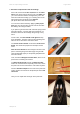
Erwin XL slope building Instruction August 2018 7. Electronic components inside the fuselage First of all, thread a steel wire of 1,5 mm into the outer tubes of the push rods. By this, they get a lot stiffer and you can thread them into the fuselage easily. Once the tubes are inside the fuselage, you can bring them to the right position from outside by using magnets. (On photo white outer tubes were used.
Erwin XL slope building Instruction August 2018 We use a very simple solution to mount the canopy. Just glue the carbon stick into the canopy. 8. Wing The openings for the servos are big enough for all appropriate standard servos including mounting frame, such as Futaba S3150. Lead the cable through the wing as shown below. The connection to the levers on the rudder goes crosswise through the wing.
Erwin XL slope building Instruction August 2018 For gluing the lever use epoxy-glue with cotton flocks. When fitting the lever in the correct position, notice that the hole in the lever should be situated vertically above the hinge line. To connect the servos to the levers use two connectors M2,5mm. In between, use a welding rod (diameter 2mm), which you solder inside the both connectors. To find the right length of the welding rod put all servos in 0-position.
Erwin XL slope building Instruction August 2018 9. Installation of antenna If you want to install 2,4 Ghz, let the antennas stand out of the carbon fuselage as shown on the photo of Elvira. The angle between the antennas should be 90°. 35 / 40 MHz: As Erwin XL slope is completely made of carbon, a part of the antenna must be situated outside the model. One possiblity is to „extend“ the fuselage at the rear end with a steel wire of about 450mm. Fix the end of the antenna to this steel wire.
Erwin XL slope building Instruction August 2018 BEFORE THE FIRST FLIGHT 10. Ballast system You can easily change the weight by varying between the different connectors. You should always use two connectors when flying Erwin XL slope. If the glider accelerates too slowly, don’t hesitate to add further weight. Erwin XL slope can do well with more weight, in the air as well as when landing. (Photos made from an older version of the root rib.
Erwin XL slope building Instruction August 2018 11. Fixing of the wing When attaching the wings, make sure that the connector will not be postponed again. First, push the connector into the first wing half as far as possible. Note, that the shorter part of the connector should disappear inside the wing. Then, push the fuselage onto the connector and finally the 2nd wing half. Close the gap between wings and fuselage with adhesive tape. By this way, the wing halves are fixed to the fuselage. 12.