
User's Manual
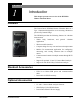
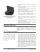
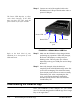
Table Of Contents
- Introduction
- Getting Started
- Making a Measurement
- Technical Specifications
- Functions Measured
- General Characteristics
- Physical Characteristics
- Data Communication Characteristics
- Electrical Characteristics
- Adaptor Resonances and Frequency Responses
- Reference Values
- Typical Measurement Ranges
- Frequency Weighting Curves
- Fa (Flat 0.4 Hz to 100 Hz)
- Fb (Flat 0.4 Hz to 1260 Hz) Frequency Weighting
- Fc (Flat 6.3 Hz to 1260 Hz), Wh, and Wf Frequency Weighting.
- Wm, Wc, and Wd Frequency Weightings
- We, Wj, and Wk Frequency Weighting
- Wg Frequency Weighting (Defined in BS6841:1987)
- Wm (Whole Body) Frequency Weighting
- Typical Measurements Ranges
- Standards Met
- Glossary
- RMS Acceleration
- RMS Acceleration in Decibels
- Allowed Exposure Time
- Energy Equivalent RMS Acceleration
- Running RMS Acceleration LINEAR
- Running RMS Acceleration EXPONENTIAL
- Vibration Dose Value
- Maximum Transient Vibration Value
- Minimum Transient Vibration Value
- Long Term Maximum Peak
- Short Term Maximum Peak
- Long Term Crest Factor
- Short Term Crest Factor
- Summed Instantaneous Acceleration
- Regulatory Compliance Statement
1-2 Transducer Selection HVM200 Manual
• Larson Davis CCS048 Arm Band for wearing the
HVM200
• Larson Davis SEN041F accelerometer for Hand-Arm
vibration measurements
• Larson Davis SEN020 accelerometer for Hand-Arm and
general vibration measurements
• Larson Davis SEN027 Seat Adapter, accelerometer, and
adapter for whole-body vibration measurements
• Larson Davis ADP063, ADP080A, ADP081A, and
ADP082A adapters for accelerometer placement
Optional Larson Davis CCS047
Hard Shell Case
• Larson Davis CBL210-05, CBL216, and CBL217-01
cables for connection between accelerometers and
HVM200 meter.
• Larson Davis 394C06 Hand-held Shaker for vibrational
measurement verification
• Larson Davis CCS047 Hard Shell Case for transport and
protection of HVM200 and accessories
Transducer Selection
The HVM200 requires a transducer to convert physical
vibration quantities into measurable, electrical signals. In
selecting a transducer for the HVM200, consider the
following
ICP
®
or Charge Accelerometers
The HVM200 has built-in ICP
®
power supplies and charge
amplifiers. This allows the HVM200
to interface directly with ICP or
charge transducers, and eliminates
the need for external signal
conditioning.
•ICP
accelerometers are also called “Voltage Mode” or
“Low impedance” and may be known by various other
vendor trade names. ICP is PCB’s registered trademark
which stands for “Integrated Circuit Piezoelectric” and
identifies PCB sensors which incorporate built-in, signal
conditioning electronics. The built-in electronics serve to
convert the high impedance charge signal that is
generated by the piezoelectric sensing element to a
usable low impedance voltage signal which can be
readily transmitted over ordinary 2 wire or coaxial cables
to any voltage readout or recording device. The low
impedance signal can be transmitted over long cable
distances and used in dirty field or factory environments
with little signal degradation