Motherboard User’s Guide This publication, including photographs, illustrations and software, is under the protection of international copyright laws, with all rights reserved. Neither this manual, nor any of the material contained herein, may be reproduced without the express written consent of the manufacturer. The information in this document is subject to change without notice.
Motherboard User’s Guide Table of Contents Trademark ................................................................................... i Features and Checklist Translation ........................................ v Chapter 1: Introduction ............................................................ 1 Key Features ........................................................................................ 2 Package Contents ................................................................................
Motherboard User’s Guide Static Electricity Precautions Static electricity could damage components on this motherboard. Take the following precautions while unpacking this motherboard and installing it in a system. 1. Don’t take this mainboard and components out of their original static-proof package until you are ready to install them. 2. While installing, please wear a grounded wrist strap if possible.
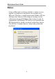
Motherboard User’s Guide Notice: Owing to Microsoft’s certifying schedule is various to every supplier, we might have some drivers not certified yet by Microsoft. Therefore, it might happen under Windows XP that a dialogue box (shown as below) pop out warning you this software has not passed Windows Logo testing to verify its compatibility with Windows XP. Please rest assured that our RD department has already tested and verified these drivers.
Motherboard User’s Guide Traduction des Caractéristiques & Liste de contrôle Liste de contrôle Le coffret de votre carte mère contient les éléments suivants: • La carte mère • Le Manuel utilisateur • Un câble plat pour lecteur de disquette (optionnel) • Une câble plat pour lecteur IDE • CD de support de logiciels Caractéristiques Prise en charge du Processeur Socket-478 • Supporte le Processeur Intel Pentium 4 series avec la Technologie Hyper Threading • Supporte un Bus Avant allant jusqu’à 800 MHz La techn
Motherboard User’s Guide • Supporte maîtrise de bus Ultra DMA IDE avec vitesse de transfert de 33/66/ 100 Mo/sec ATA Série • Deux ATA Série connecteurs • Vitesse de transfert supérieure au meilleur ATA (~150 Mo/s) avec extensibilité aux vitesses supérieures • Comptage de broche faible pour l’hôte et les périphériques AC’97 Codec • L’architecture matérielle 6-CH permet au southbridge multi-canal de lire l’audio 6CH • Compatible Intel AC’97 (REV. 2.
Motherboard User’s Guide • Conforme aux Spécifications d’Interface de Contrôleur d’Hôte Universel Révision 1.
Motherboard User’s Guide Checkliste Funktionen & Checkliste Die Verpackung Ihres Motherboards enthält folgende Teile: • Motherboard • Handbuch • Bandkabel für Floppylaufwerke (optional) • Bandkabel für IDE-Laufwerke • Software -CD Ausstattung Unterstütz Socket-478-Prozessoren • Unterstützung für Intel Pentium 4-Prozessor mit “Hyper-Threading”-Technologie • Unterstützung von bis zu 800 MHz Front-Side Bus “Hyper-Threading”-Technologie läßt das Betriebssystem glauben, es sei an zwei Prozessoren angeschloss
Motherboard User’s Guide • Unterstützung für IDE Ultra DMA-Busmastering mit Transferraten von 33/66/ 100 MB/Sek Serial ATA • Zwei Serial ATA Headers • Datentransferrate übertrifft beste ATA-Werte (~150 MB/Sek.); höhere Transferraten möglich • Low Pin Count (LPC) für Host und Geräte AC’97 Codec • 6-CH Hardware-Architektur erlaubt einen Multikanal south bridge für die 6CH Tonwiedergabe • Kompatibel mit Intel AC’97 (REV. 2.
Motherboard User’s Guide USB2.0 • Entspricht Universal Serial Bus-Spezifikation, Revision 2.0 • Entspricht Intels Enhanced Host Controller Interface-Spezifikation, Revision 1.0 • Entspricht Universal Host Controller Interface -Spezifikation Revision 1.
Motherboard User’s Guide Lista Traduzione Funzioni e Lista L’imballo della scheda madre é composto da: • La scheda madre • Il manuale • Una piattina per il collegamento dei drive (opzionale) • Una piattina IDE • Il CD con il Software di supporto Caratteristiche Dotata di Socket 478 per Processori • Supporta CPU Processori Intel Pentium serie 4 con tecnologia Hyper Threading • Supporta fino a 800 MHz Front Side Bus La tecnologia Hyper-Threading permette al sistema operative di essere dotato di due procre
Motherboard User’s Guide ATA Seriale • Due connettori Serial ATA • Altissima velocità di trasferimento dati ATA (~150 MB/s) con la possibilità di scalabilità della velocità stessa verso valori piú alti • Pin Count ridotto sia per l’host sia per le periferich AC’97 Codec • Architettura hardware 6-CH che permette l’utilizzo del “multi-channel south bridge” per la riproduzione 6CH • Compatibilità con lo standard Intel AC’97 (REV. 2.
Motherboard User’s Guide • Il root hub è composto in 4 porte in downstream facing con ricevitore physical layer integrato condiviso dall’Host Controller UHCI e EHCI sino a otto porte funzionali • Supporto per interfaccia risparmio energia bus PCI specifiche release 1.1 • Supporto per tutte le porte downstream precedenti Nota: Alcune specifiche hardware ed elementi software sono soggetti a variazioni senza preavviso.
Motherboard User’s Guide Traducción de Características & Lista LISTA DE VERIFICACIÓN El paquete de su placa principal contiene los sigtes.
Motherboard User’s Guide ATA Serial • Dos conectores Serial ATA • Índice de transferencia que excede el mejor ATA (~150 MB/s) con escalabilidad a índices superiores • Cuenta de pin baja para ambos anfitrión y dispositivos AC’97 Codec • Arquitectura de hardware 6-CH permite south bridge de multicanal para reproducir sonido 6CH • Compatible con Intel AC’97 (REV. 2.
Motherboard User’s Guide • Dispositivo PCI multi-función se consiste de dos centros de Controlador Anfitrión UHCI para señalización de velocidad completa/baja y un centro de Controlador Anfitrión EHCI para señalización de alta velocidaa • El Hub de raíz consiste de 4 puertos downstream con transreceptores de capa física integrados compartidos por el Controlador Anfitrión UHCI y EHCI, hasta ocho puertos funcionales • Soporta Especificación de Interfaz de Administración de Energía de BUS PCI versión 1.
Motherboard User’s Guide Tradução da Lista & Características Lista de verificação A embalagem da sua placa principal contém os seguintes itens: • A placa principal • O Manual do Utilizador • Um cabo para a unidade de disquetes (opcional) • Um cabo para a unidade IDE • CD de suporte para o software Características Suporte do Processador Socket-478 • Suporta Processador série Intel Pentium 4 com Tecnologia Hyper Threading • Suporta até 800 MHz Front-Side Bus Tecnologia Hyper-Threading que permite o sistema o
Motherboard User’s Guide Série ATA • Dois conectores Série ATA • Razão de transferência excedendo o melhor ATA (~150 MB/s) com escalabilidade para razões mais altas • Contagem baixa de pin para ambos os dispositivos e host AC’97 Codec • Arquitetura 6-CH hardware permite que a ponte sul de canais múltiplos reapresente o áudio 6CH • Intel® AC’97 (REV. 2.
Motherboard User’s Guide USB 2.0 • Compatível com Universal Serial Bus Revisão 2.0 da especificação • Compatível com controlador Enhanced Host da Intel Revisão 1.0 da especificação da interface • Compatível com controlador Universal Host Revisão 1.
Motherboard User's Manual 功能和检查单翻译 检查单 您的主板包装含有以下项目: • 主板 • 用户手册 • 一根磁盘驱动器扁平电缆(可选) • 一根 IDE 驱动器扁平电缆 • 软件支持 CD 功能 支持 Socket-478 处理器 • 支持带有/多线程技术的 Intel Prescott/Pentium 4 系列处理器 • 支持 800 MHz前端总线 “多线程”技术可以让操作系统认为自己连接了两个处理器,允许两个线程并行运 行,每个线程位于同一处理器中的单独“逻辑”处理器中。 芯片组 芯片组包含Intel 865PE 北桥 和Intel 82801EB I/O Controller Hub (ICH5), 它基于 一种新型的、可扩展的架构,能提供已经证明的可靠性和高性能。 • 支持集成图形设备 (IGD) 或 AGP 外部图形设备。AGP 接口支持 1X/4X/8X AGP 数据传输和 4X/8X AGP 快写功能。 • 支持 4 GB 系统内存,使用双模式下的 DDR400 内存最大带宽可达 6.
Motherboard User's Manual Serial ATA • 2 个Serial ATA 接口 • 传输速率超过 ATA (~150 MB/s),可扩展到更高速率 • 主机和设备管脚数量少 AC’97 Codec • 6-CH 硬件结构,允许多声道南桥播放 6CH 音频 • 符合 Intel AC’97 (REV. 2.3) 规格,满足 Microsoft PC2001 要求 • 内建耳机缓存和内部 PLL,后者可节省额外的晶体 • 线入/后部输出共享同一插孔,中置/低音共享 MIC 插孔 • 支持数字 S/PDIF OUT • CRL 3D:与基于 HRTF 的 BS3D 兼容的音频引擎 集成 I/O 端口 此主板具有完整的 I/O 端口和插孔: • 2 个用于连接鼠标和键盘的 PS/2 端口 • 1 个串口 • 1 个并口 • 1 个LAN端口(可选) • 4 个后面板 USB2.0 端口 • 麦克风、线入和线出声音插孔 快速以太网 LAN (可选) ·板上集成千兆 LAN: -集成 10/100/1000 收发器 -带续页能力的自协商 -支持全双工数据流控制 (IEEE 802.
Motherboard User's Manual • • 支持 1.
Chapter 1: Introduction Chapter 1 Introduction This motherboard has a Socket-478 supporting Intel Prescott/ Pentium 4 with Hyper-Threading Technology processors with Front-Side Bus (FSB) speeds up to 800 MHz. Hyper-Threading Technology, designed to take advantage of the multitasking features in Windows XP, gives you the power to do more things at once.
Motherboard User’s Guide Note: You must initiate the HT CPU function through BIOS setup. It is strongly recommended you refer to Page 40 for relative details.
Chapter 1: Introduction • Integrated Serial ATA Host Controller: Independent DMA operation and Data Transfer Rate up to 1.5Gb/s(150MB/s) Memory Support • Four 184-pin DIMM sockets for DDR SDRAM memory modules • Supports DDR400 memory bus • Maximum installed memory is 4GB Expansion Slots • One CNR slot • One 8x/4x AGP slot • Five 32-bit PCI slots for PCI 2.
Motherboard User’s Guide • • Digital S/PDIF OUT Support CRL® 3D: HRTF based BS3D compatible audio engine Onboard I/O Ports The motherboard has a full set of I/O ports and connectors: • Two PS/2 ports for mouse and keyboard • One serial port • One parallel port • One LAN port (optional) • Four back-panel USB2.
Chapter 1: Introduction • PCI multi-function device consists of two UHCI Host Controller cores for full-/low-speed signaling and one EHCI Host Controller core for high-speed signaling • Root hub consists 4 downstream facing ports with integrated physical layer transceivers shared by UHCI and EHCI Host Controller, up to eight functional ports • Support PCI-Bus Power Management Interface Specification release 1.
Motherboard User’s Guide Dimensions • ATX form factor of 305 x 244 mm Note: Hardware specifications and software items are subject to change without notification. Package Contents Your motherboard package ships with the following items: • • • • • The motherboard The User’s Guide One diskette drive ribbon cable (optional) One IDE drive ribbon cable The Software support CD Optional Accessories You can purchase the following optional accessories for this motherboard. • The Extended USB module • The CNR v.
Chapter 2: Motherboard Installation Chapter 2 Motherboard Installation To install this motherboard in a system, please follow these instructions in this chapter: • • • • • • Identify the motherboard components Install a CPU Install one or more system memory modules Make sure all jumpers and switches are set correctly Install this motherboard in a system chassis (case) Connect any extension brackets or cables to headers/ connectors on the motherboard • Install peripheral devices and make the appropriate co
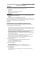
Motherboard User’s Guide Motherboard Components Socket-478 PWR/NBFAN CPU FAN IR1 ATX2 FLOPPY IO PORTS DDR ATX3 IDE JPX AGP1 JP1 CD1 SATA AUDIO2 CNR1 PCI LABEL DIMM1--4 IDE1/2 ATX3 ATX2 USB2/3 FLOPPY PANEL1 SYSFAN JP1 JPX SPK1 USB2/3 SYSFAN SPK1 PANEL1 COMPONENTS Four 184-pin DDR SDRAM sockets Primary/Secondary IDE connectors Standard 4-Pin ATX Power connector Standard 20-Pin ATX Power connector Front Panel USB headers Floppy Disk Drive connector Front Panel Switch/LED header System Fan connecto
Chapter 2: Motherboard Installation LABEL IR1 SATA1/2 PCI 1-5 CD1 AUDIO2 CPUFAN PWR/NBFAN CNR1 AGP1 COMPONENTS Infrared Port header Serial ATA connectors 32-bit PCI slots Analog Audio Input header Front Panel Audio header CPU Fan connector Power/NB Fan connector Communications Networking Riser slot Accelerated Graphics Port slot I/O Ports The illustration below shows a side view of the built-in I/O ports on the motherboard.
Motherboard User’s Guide Installing the Processor This motherboard has a Socket 478 processor socket. When choosing a processor, consider the performance requirements of the system. Performance is based on the processor design, the clock speed and system bus frequency of the processor, and the quantity of internal cache memory and external cache memory. CPU Installation Procedure Follow these instructions to install the CPU: pin1 1 CPUFAN Socket-478 1 Unhook the locking lever of the CPU socket.
Chapter 2: Motherboard Installation 3 4 5 6 Push the locking lever down and hook it under the latch on the edge of socket. Apply thermal grease to the top of the CPU. Install the cooling fan/heatsink unit onto the CPU, and secure them all onto the socket base. Plug the CPU fan power cable into the CPU fan connector (CPUFAN) on the motherboard. Installing Memory Modules This motherboard accommodates four 184-pin 2.
Motherboard User’s Guide Memory Module Installation Procedure These modules can be installed with up to 4 GB system memory. Refer to the following to install the memory module. 1. 2. Push down the latches on both sides of the DIMM socket. Align the memory module with the socket. There is a notch on the DIMM socket that you can install the DIMM module in the correct direction. Match the cutout on the DIMM module with the notch on the DIMM socket. 3.
Chapter 2: Motherboard Installation Jumper Settings Connecting two pins with a jumper cap is SHORT; removing a jumper cap from these pins, OPEN. 1 JPX 1 JP1 JP1: Clear CMOS Jumper Use this jumper to clear the contents of the CMOS memory. You may need to clear the CMOS memory if the settings in the Setup Utility are incorrect and prevent your motherboard from operating.
Motherboard User’s Guide Install the Motherboard Install the motherboard in a system chassis (case). The board is an ATX size motherboard. You can install this motherboard in an ATX case. Make sure your case has an I/O cover plate matching the ports on this motherboard. Install the motherboard in a case. Follow the case manufacturer’s instructions to use the hardware and internal mounting points on the chassis.
Chapter 2: Motherboard Installation Connect the case switches and indicator LEDs to the PANEL1 header. Please refer to the following list of the PANEL1 pin assignments.
Motherboard User’s Guide AUDIO2: Front Panel Audio Header This header allows the user to install auxiliary front-oriented microphone and line-out ports for easier access. Pin Signal Pin Signal 1 AUD_MIC 2 AUD_GND 3 AUD_MIC_BIAS 4 AUD_VCC 5 AUD_FPOUT_R 6 AUD_RET_R 7 HP_ON 8 KEY 9 AUD_FPOUT_L 10 AUD_RET_L USB2/USB3: Front panel USB Header The motherboard has USB ports installed on the rear edge I/O port array. Additionally, some computer cases have USB ports at the front of the case.
Chapter 2: Motherboard Installation IR1: Infrared Header The infrared port allows the wireless exchange of information between your computer and similarly equipped devices such as printers, laptops, Personal Digital Assistants (PDAs), and other computers. Pin Signal Pin Signal 1 NC 2 KEY 3 +5V 4 GND 5 IRTX 6 IRRX 1. 2. Locate the infrared port-IR1 header on the motherboard.
Motherboard User’s Guide Floppy Disk Drive The motherboard ships with a floppy disk drive cable that can support one or two drives. Drives can be 3.5" or 5.25" wide, with capacities of 360K, 720K, 1.2MB, 1.44MB, or 2.88MB. Install your drives and connect power from the system power supply. Use the cable provided to connect the drives to the floppy disk drive connector FLOPPY. IDE Devices IDE devices include hard disk drives, high-density diskette drives, and CD-ROM or DVD-ROM drives, among others.
Chapter 2: Motherboard Installation Serial ATA Devices The Serial ATA (Advanced Technology Attachment) is the standard interface for the IDE hard drives, which is designed to overcome the design limitations while enabling the storage interface to scale with the growing media rate demands of PC platforms. It provides you a faster transfer rate of 150 MB/s. If you have installed a Serial ATA hard drive, you can connect the Serial ATA cables to the Serial ATA hard drive or the connecter on the motherboard.
Motherboard User’s Guide When you first start up your system, the BIOS should automatically detect your CD-ROM/DVD drive. If it doesn’t, enter the Setup Utility and configure the CD-ROM/DVD drive that you have installed. On the motherboard, locate the 4-pin header CD1. Pin 1 2 3 4 Signal CD IN L GND GND CD IN R Expansion Slots This motherboard has one AGP, one CNR and five 32-bit PCI slots.
Chapter 2: Motherboard Installation Follow the steps below to install an AGP/CNR/PCI expansion card. 1. 2. 3. 4. Locate the AGP, CNR or PCI slots on the motherboard. Remove the blanking plate of the slot from the system chassis. Install the edge connector of the expansion card into the slot. Ensure the edge connector is correctly seated in the slot. Secure the metal bracket of the card to the system chassis with a screw.
Motherboard User’s Guide Chapter 3 BIOS Setup Utility Introduction The BIOS Setup Utility records settings and information of your computer, such as date and time, the type of hardware installed, and various configuration settings. Your computer applies the information to initialize all the components when booting up and basic functions of coordination between system components. If the Setup Utility configuration is incorrect, it may cause the system to malfunction.
Chapter 3: BIOS Setup Utility Running the Setup Utility Every time you start your computer, a message appears on the screen before the operating system loading that prompts you to “Hit if you want to run SETUP”. Whenever you see this message, press the Delete key, and the Main menu page of the Setup Utility appears on your monitor.
Motherboard User’s Guide Standard CMOS Setup Page This page displays a table of items defining basic information about your system. CMOS SETUP UTILITY – Copyright (C) 1985-2003, American Megatrends, Inc.
Chapter 3: BIOS Setup Utility Floppy A/B These items set up size and capacity of the floppy diskette drive(s) installed in the system. Advanced Setup Page This page sets up more advanced information about your system. Handle this page with caution. Any changes can affect the operation of your computer. CMOS SETUP UTILITY – Copyright (C) 1985-2003, American Megatrends, Inc.
Motherboard User’s Guide BootUp Num-Lock This item determines if the Num Lock key is active or inactive at system start-up time. Boot to OS/2 > 64MB Enable this item if you are booting the OS/2 operating system and you have more than 64MB of system memory installed. Graphic Win Size This item defines the size of aperture if you use a graphic adapter. Configure DRAM Timing By SPD This item allows you to enable or disable the DRAM timing defined by the Serial Presence Detect electrical.
Chapter 3: BIOS Setup Utility Features Setup Page This page sets up some parameters for peripheral devices connected to the system. CMOS SETUP UTILITY – Copyright (C) 1985-2003, American Megatrends, Inc. Features Setup OnBoard Floppy Controller Enabled Help Item Serial Port1 Address 3F8/IRQ4 OnBoard IR Port Disabled Allows BIOS to Parallel Port Address 378 Enable or Disable Parallel Port Mode ECP Floppy Controller.
Motherboard User’s Guide Parallel Port Mode This item decides the parallel port mode. You can select SPP (Standard Parallel Port), ECP (Extended Capabilities Port), EPP (Enhanced Parallel Port), or ECP + EPP. ECP Mode DMA Channel This item assigns a DMA channel to the parallel port. The options are 0, 1 and 3. Parallel Port IRQ This item assigns either IRQ 5 or 7 to the parallel port.
Chapter 3: BIOS Setup Utility Option Disabled Function Disabled S-ATA Controller Primary: 2 IDE Drives Enhanced Mode Secondary: 2 IDE Drives S-ATA: 2 S-ATA Drives SATA Only Combine Mode Only support SATA mode Primary: 2 IDE Drives S-ATA: 2 S-ATA Drives Serial ATA Port0/1 Mode Use this item to decide the sequence of the Serial ATA devices. Power Management Setup Page This page sets some parameters for system power management operation.
Motherboard User’s Guide ACPI Aware O/S This item supports ACPI (Advanced Configuration and Power management Interface). Use this item to enable or disable the ACPI feature. Power Management Use this item to enable or disable a power management scheme. If you enable power management, you can use the items below to set the power management operation. Both APM and ACPI are supported.
Chapter 3: BIOS Setup Utility Keyboard Power On If you enable this item, system can automatically resume by pressing any keys, hot or power key on the keyboard or typing in the password. You must use an ATX power supply in order to use this feature. PCI / Plug and Play Setup Page This page sets up some parameters for devices installed on the PCI bus and those utilizing the system plug and play capability. CMOS SETUP UTILITY – Copyright (C) 1985-2003, American Megatrends, Inc.
Motherboard User’s Guide BIOS Security Features Setup Page This page helps you install or change a password. CMOS SETUP UTILITY – Copyright (C) 1985-2003, American Megatrends, Inc. BIOS Security Features Setup Security Settings Help Item Supervisor Password : Not Installed Change Supervisor Password Press Enter Install or Change the password.
Chapter 3: BIOS Setup Utility CPU PnP Setup Page This page helps you manually configure the mainboard for the CPU. The system will automatically detect the type of installed CPU and make the appropriate adjustments to the items on this page. CMOS SETUP UTILITY – Copyright (C) 1985-2003, American Megatrends, Inc. CPU PnP Setup Manufacturer Intel Help Item Ratio Status Locked Ratio Actual Value 18 Sets the ration between CPU Ration CMOS Setting 18 Core Clock and the FSB DRAM Frequency Auto Frequency.
Motherboard User’s Guide Hardware Monitor Page This page sets up some parameters for the hardware monitoring function of this motherboard. CMOS SETUP UTILITY – Copyright (C) 1985-2003, American Megatrends, Inc. Hardware Monitor Setup *** System Hardware Monitor*** Help Item Vcore 1.467V Vddq 1.580V Vcc5V 5.012V SB3V 3.
Chapter 3: BIOS Setup Utility Load Optimal Settings If you select this item and press Enter a dialog box appears. If you press Y, and then Enter, the Setup Utility loads a set of failsafe default values. These default values are not very demanding and they should allow your system to function with most kinds of hardware and memory chips. Note: It is highly recommend that users enter this option to load optimal default values for accessing the best performance.
Motherboard User’s Guide Chapter 4 Software & Applications Introduction This chapter describes the contents of the support CD-ROM that comes with the motherboard package. The support CD-ROM contains all useful software, necessary drivers and utility programs to properly run our products. More program information is available in a README file, located in the same directory as the software. To run the support CD, simply insert the CD into your CD-ROM drive.
Chapter 4: Software & Applications Installing Support Software 1 2 3 Insert the support CD-ROM disc in the CD-ROM drive. When you insert the CD-ROM disc in the system CDROM drive, the CD automatically displays an Auto Setup screen. The screen displays three buttons of Setup, Browse CD and Exit on the right side, and three others Setup, Application and ReadMe at the bottom. Please see the following illustration. The Setup button runs the software auto-installing program as explained in next section.
Motherboard User’s Guide Auto-Installing under Windows 98/ME/2000/XP If you are under Windows 98/ME/2000/XP, please click the Setup button to run the software auto-installing program while the Auto Setup screen pops out after inserting the support CD-ROM: 1 The installation program loads and displays the following screen. Click the Next button. 2 Select the items that you want to setup by clicking on it (the default options are recommended). Click the Next button to proceed.
Chapter 4: Software & Applications Installing under Windows NT or Manual Installation If you are under Windows NT, the auto-installing program doesn’t work out; or you have to do the manual installation, please follow this procedure while the Auto Setup screen pops out after inserting the support CD-ROM: 1 2 3 Click the ReadMe to bring up a screen, and then click the Install Path at the bottom of the screen. Find out your mainboard model name and click on it to obtain its correct driver directory.
Motherboard User’s Guide Hyper-Threading CPU You must update BIOS to initiate BIOS Hyper-Threading Function and use HT CPU function under WinXP Operating System; if not, please disable this option. • When BIOS detects the HT CPU, it shows the “HyperThreading Function (default Disabled)” option, which you must set Enabled if you want to test HT CPU function. If there is no HT CPU, this option is hidden and default Disabled. • You must re-install WINXP to activate the HT CPU function.
Motherboard User’s Guide Appendix Intel USB 2.0 Driver Limitations & Manual Installation • USB2.0 Driver only supports the Operating System WinXP/ Win2K, and WinME & Win98SE driver only supports USB 1.1 function. Note: If your Operating System Windows XP has the Service Pack, you can directly access the driver regardless of the driver limitation. • You must follow these steps to manually install the WinXP driver; otherwise, you can’t succeed this driver’s installation. 1.
6.Go on executing the manual installation as below: 6-1 Disable Windows File Protection (WFP) −From Start button/run/Regedit. Software\Microsoft\Windows NT\ CurrentVersion\Winlogon\SFCDisable = 1 6-2 Copy all USB files from CD to HDD. −Copy all test drivers to %windir%\driver cache\i386 −Copy all test drivers to You need to copy file to this directory first. Oterwise, Windows XP will replace file from this directory to system32\drivers. −Copy all test drivers to %windir%\system32\drivers.