Motherboard User’s Guide This publication, including photographs, illustrations and software, is under the protection of international copyright laws, with all rights reserved. Neither this user’s guide, nor any of the material contained herein, may be reproduced without the express written consent of the manufacturer. The information in this document is subject to change without notice.
Motherboard User’s Guide Table of Contents Trademark ............................................................................................................ i Static Electricity Precautions ......................................................................................... i Pre-Installation Inspection ............................................................................................. i Chapter 1: Introduction ............................................................................
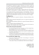
Motherboard User’s Guide Notice: 1 Owing to Microsoft’s certifying schedule is various to every supplier, we might have some drivers not certified yet by Microsoft. Therefore, it might happen under Windows XP that a dialogue box (shown as below) pop out warning you this software has not passed Windows Logo testing to verify its compatibility with Windows XP. Please rest assured that our RD department has already tested and verified these drivers.
Motherboard User’s Guide Chapter 1 Introduction This motherboard has a LGA1155 socket for latest 2nd Generation Intel® CoreTM Family processors for high-end business or personal desktop markets. This motherboard is based on Intel® H61 Express Chipset for best desktop platform solution. H61 is a single-chip, highly integrated, high performance HyperThreading peripheral controller, unmatched by any other single chip device controller.
Motherboard User’s Guide Chipset The Intel® H61 Chipset is a single-chip with proven reliability and performance. • High performance Host Interface: Supports the LGA1155 socket for latest 2nd Generation Intel® CoreTM Family processors • System Memory Controller Support: DDR3 SDRAM with up to maximum memory of 16 GB* • Support two PCI Express x1 slots • Integrade Serial ATA Host Controller with Data transfer rates up to 3.
Chapter 1: Introduction Onboard LAN (Optional) • • • • • • Supports PCI ExpressTM 1.1 Integrated 10/100/1000 transceiver Wake-on-LAN and remote wake-up support Supports PCI ExpressTM 1.1 Integrated 10/100 transceiver Wake-on-LAN and remote wake-up support Onboard I/O Ports • Two PS/2 ports for mouse and keyboard • One VGA port • One LAN port • One HDMI port • Four USB 2.
Motherboard User’s Guide Package Contents Your motherboard package ships with the following items: The motherboard Two Serial ATA cables The Software support disk Optional Accessories You can purchase the following optional accessories for this motherboard. The Extended USB module The Serial ATA power cable Note: You can purchase your own optional accessories from the third party, but please contact your local vendor on any issues of the specification and compatibility.
Chapter 2: Motherboard Installation Chapter 2 Motherboard Installation To install this motherboard in a system, please follow these instructions in this chapter: Identify the motherboard components Install a CPU Install one or more system memory modules Make sure all jumpers and switches are set correctly Install this motherboard in a system chassis (case) Connect any extension brackets or cables to headers/connectors on the motherboard Install peripheral devices and make the appropriate conn
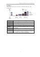
Motherboard User’s Guide Motherboard Components LABEL 1. CPU Socket 2. CPU_FAN 3. DDR3_1~2 4. ATX_POWER 5. SPI_DEBUG 6. SATA1~4 7. F_PANEL 8. F_USB1~2 9. CASE 10. ME_UNLOCK 11. TPM 12. SPK 13. CLR_CMOS 14. COM 15. SPDIFO 16. SYS_FAN 17. F_AUDIO 18. PCIE1~2 19. PCIEX16 20. ATX12V COMPONENTS LGA1155 socket for 2nd Generation Intel® CoreTM Family Processors 4-pin CPU cooling fan connector 240-pin DDR3 SDRAM slots Standard 24-pin ATX power connector SPI debug header-for factory use only Serial ATA 3.
Chapter 2: Motherboard Installation I/O Ports The illustration below shows a side view of the built-in I/O ports on the motherboard. PS/2 Mouse Use the upper PS/2 port to connect a PS/2 pointing device. PS/2 Keyboard Use the low er PS/2 port to connect a PS/2 keyboard. HDMI Port Connect the HDMI port to the monitor. VGA Port Connect your monitor to the VGA port. LAN Port Connect an RJ-45 jack to the LAN port to connect your computer to the Netw ork. Use the USB 2.0 ports to connect USB 2.0 devices.
Motherboard User’s Guide Installing the Processor This motherboard has a LGA1155 socket for latest 2nd Generation Intel® Core TM Family processors. When choosing a processor, consider the performance requirements of the system. Performance is based on the processor design, the clock speed and system bus frequency of the processor, and the quantity of internal cache memory and external cache memory. CPU Installation Procedure Follow these instructions to install the CPU: A.
Chapter 2: Motherboard Installation D. Inserting the Package · Grasp the package. Ensure to grasp on the edge of the substrate. · Make sure pin 1 indicator is on your bottom-left side. · Aim at the socket and place the package carefully into the socket by purely vertical motion. E. Closing the Load Plate · Rotate the load plate onto the package IHS (Intergraded Heat Spreader). · Engage the load lever while pressing down lightly onto the load plate. · Secure the load lever with the hook under retention tab.
Motherboard User’s Guide Installing Memory Modules This motherboard accommodates two 240-pin DIMM sockets for unbuffered DDR3 1333/1066 memory modules, and maximum 16 GB* installed memory. Note: Due to the DRAM maximum size is 4 GB at present, the memory maximum size we have tested is 8 GB.
Chapter 2: Motherboard Installation Memory Module Installation Procedure These modules can be installed with up to 16 GB* system memory. Refer to the following to install the memory module. 1. Push down the latches on both sides of the DIMM socket. 2. Align the memory module with the socket. There is a notch on the DIMM socket that you can install the DIMM module in the correct direction. Match the cutout on the DIMM module with the notch on the DIMM socket. 3.
Motherboard User’s Guide Jumper Settings Connecting two pins with a jumper cap is SHORT; removing a jumper cap from these pins, OPEN. CLR_CMOS: Clear CMOS Jumper Use this jumper to clear the contents of the CMOS memory. You may need to clear the CMOS memory if the settings in the Setup Utility are incorrect and prevent your motherboard from operating. To clear the CMOS memory, disconnect all the power cables from the motherboard and then move the jumper cap into the CLEAR setting for a few seconds.
Chapter 2: Motherboard Installation Install the Motherboard Install the motherboard in a system chassis (case). The board is a Micro ATX size motherboard. You can install this motherboard in an ATX case. Make sure your case has an I/O cover plate matching the ports on this motherboard. Install the motherboard in a case. Follow the case manufacturer’s instructions to use the hardware and internal mounting points on the chassis.
Motherboard User’s Guide Connecting Optional Devices Refer to the following for information on connecting the motherboard’s optional devices: SPK: Speaker Header Connect the cable from the PC speaker to the SPK header on the motherboard.
Chapter 2: Motherboard Installation COM: Onboard Serial Port Header Connect a serial port extension bracket to this header to add a second serial port to your system. Pin 1 3 5 7 9 Signal DCDB SOUTB GND RTSB RI Pin 2 4 6 8 10 Signal SINB DTRB DSRB CTSB KEY F_AUDIO: Front Panel Audio Header This header allows the user to install auxiliary front-oriented microphone and lineout ports for easier access.
Motherboard User’s Guide TPM: Trusted Platform Module header Trusted platform module (TPM) is a published specification detailing a microcontrollerthat can store secured information, and implementations of that specification.
Chapter 2: Motherboard Installation Install Other Devices Install and connect any other devices in the system following the steps below. Serial ATA Devices The Serial ATA (Advanced Technology Attachment) is the standard interface for the IDE hard drives, which is designed to overcome the design limitations while enabling the storage interface to scale with the growing media rate demands of PC platforms. It provides you a faster transfer rate of 3.0 Gb/s.
Motherboard User’s Guide Expansion Slots This motherboard has one PCI Express x16, two PCI Express x1 slots. Follow the steps below to install an PCI Express expansion card. 1 Locate the PCI Express slot on the motherboard. 2 Remove the blanking plate of the slot from the system chassis. 3 Install the edge connector of the expansion card into the slot. Ensure the edge connector is correctly seated in the slot. 4 Secure the metal bracket of the card to the system chassis with a screw.
Chapter 2: Motherboard Installation PCI Express x16 Slot You can install an external PCI Express graphics card that is fully compliant to the PCI Express Base Specification revsion 2.0. PCI Express Slots You can install two external PCI Express graphics cards that are fully compliant to the PCI Express Base Specification revsion 2.0.
Motherboard User’s Guide Chapter 3 BIOS Setup Utility Introduction The BIOS Setup Utility records settings and information of your computer, such as date and time, the type of hardware installed, and various configuration settings. Your computer applies the information to initialize all the components when booting up and basic functions of coordination between system components. If the Setup Utility configuration is incorrect, it may cause the system to malfunction.
Chapter 3: BIOS Setup Utility Some options on the main menu page lead to tables of items with installed values that you can use cursor arrow keys to highlight one item, and press PgUp and PgDn keys to cycle through alternative values of that item. The other options on the main menu page lead to dialog boxes requiring your answer OK or Cancel by selecting the [OK] or [Cancel] key. If you have already changed the setup utility, press F10 to save those changes and exit the utility.
Motherboard User’s Guide Advanced Setup Page This page sets up more advanced information about your system. Handle this page with caution. Any changes can affect the operation of your computer. Main Aptio Setup Utility - Copyright (C) 2010 American Megatrends, Inc.
Chapter 3: BIOS Setup Utility Press to return to the Advanced Menu page. PC Health Status On motherboards support hardware monitoring, this item lets you monitor the paeameters for critical voltages, temperatures and fan speeds. Aptio Setup Utility - Copyright (C) 2010 American Megatrends, Inc.
Motherboard User’s Guide SMART Fan Mode (Normal) This item allows you to select the fan mode (Normal, Quiet, Silent, or Manual) for a better operation environment. If you choose Normal mode, the fan speed will be auto adjusted depending on the CPU temperature. If you choose Quite mode, the fan speed will be auto minimized for quiet environment. If you choose Silent mode, the fan speed will be auto restricted to make system more quietly.
Chapter 3: BIOS Setup Utility Power Management Setup This page sets up some parameters for system power management operation. Main Aptio Setup Utility - Copyright (C) 2010 American Megatrends, Inc.
Motherboard User’s Guide ACPI Setting The item in the menu shows the highest ACPI sleep state when the system enters suspend. Main Aptio Setup Utility - Copyright (C) 2010 American Megatrends, Inc. Advanced Chipset Tweak Boot Security Save & Exit ACPI Settings ACPI Sleep State [S3 (Suspend to RAM)] Select the highest ACPI sleep state the system will enter when the SUSPEND button is pressed. lk :Select Screen mn :Select Item Enter : Select +/- : Change Opt.
Chapter 3: BIOS Setup Utility Genuine Inter(R) CPU 0 @ 3.00GHz This is display-only field and diaplays the information of the CPU installed in your computer. EMT64 (Supported) This item shows the computer supports EMT64. Processor Speed (3000MHz) This item shows the current processor speed. Processor Stepping (206a3) This item shows the processor stepping version. Microcode Revision (8) This item shows the Microcode version. Processor Cores (4) This item shows the core number of the processor.
Motherboard User’s Guide SATA Configuration Use this item to show the mode of serial SATA configuration options. Aptio Setup Utility - Copyright (C) 2010 American Megatrends, Inc. Main Advanced Chipset Tweak Boot Security Save & Exit (1) IDE Mode. (2) AHCI Mode.
Chapter 3: BIOS Setup Utility USB Configuration Scroll to this item and press to view the following screen: Main Aptio Setup Utility - Copyright (C) 2010 American Megatrends, Inc. Advanced Chipset Tweak Boot Security Save & Exit USB Configuration Enabled/Disabled All USB Devices All USB Devices [Enabled] Legacy USB Support [Enabled] lk :Select Screen mn :Select Item Enter : Select +/- : Change Opt. F1:General Help F2:Previous Values F3:Optimized Defaults F4:Save & Exit ESC:Exit Version 2.
Motherboard User’s Guide Super IO Configuration Scroll to this item and press to view the following screen: Main Aptio Setup Utility - Copyright (C) 2010 American Megatrends, Inc. Advanced Chipset Tweak Boot Security Save & Exit Set Parameters of Serial Port 0 (COMA) Super IO Configuration f Serial Port 0 Configutation lk :Select Screen mn :Select Item Enter : Select +/- : Change Opt. F1:General Help F2:Previous Values F3:Optimized Defaults F4:Save & Exit ESC:Exit Version 2.02.1205.
Chapter 3: BIOS Setup Utility Trusted Computing Scroll to this item and press to view the following screen. Main Aptio Setup Utility - Copyright (C) 2010 American Megatrends, Inc. Advanced Chipset Tweak Boot Security Save & Exit TPM Configuration TPM Support [Enabled] Current TPM Status Information NO TPM Hardware Enables or Disables TPM support. O.S. will not show TPM. Reset of platform is required. lk :Select Screen mn :Select Item Enter : Select +/- : Change Opt.
Motherboard User’s Guide Chipset Setup Page The chipset menu items allow you to change the settings for the North chipset, South chipset and other system. Main Aptio Setup Utility - Copyright (C) 2010 American Megatrends, Inc. Advanced Chipset Tweak Boot Security Save & Exit f North Bridge f South Bridge f ME Subsystem North Bridge Parameters lk :Select Screen mn :Select Item Enter : Select +/- : Change Opt. F1:General Help F2:Previous Values F3:Optimized Defaults F4:Save & Exit ESC:Exit Version 2.02.
Chapter 3: BIOS Setup Utility IGD Multi-Monitor (Enabled) This item enables or disables IGD(Internal Graphics device) multi-monitor. Press to return to the Chipset Setup page. Multi-Monitor technology Multi-Monitor technology can help you to increase the area available for programs running on a single computer system through using multiple display devices. It is not only to increase larger screen viewing but aslo to improving personal productivity.
Motherboard User’s Guide Step 2. Install all the drivers of PCI-Express graphic cards. Click the Browse CD item, then appears the following screen. Select the driver you want to install(e.g NVIDIA GeForce 8400 GS(Microsoft Corporation-WDDM v1.1)) and double click it. Step 3. Enable IGD Multi-Monitor from BIOS. In the following BIOS screen, please set IGD Multi-Monitor to [Enabled]. Main Aptio Setup Utility - Copyright (C) 2010 American Megatrends, Inc.
Chapter 3: BIOS Setup Utility Step 4. Change the appearance of your displays under Windows 7. 1. Enter the Control Panel menu, select the Display in the All Control Panel Items and click the Screen Resolution, then appears the following screen. Show the path of the setting location Display devices Control Panel All Control Panel Items Display Screen Resolution Search Control Panel Change the apprearance of your displays 2 3 1 Display: 1.
Motherboard User’s Guide Control Panel All Control Panel Items Display Screen Resolution Search Control Panel Change the apprearance of your displays 3 2 1 Display: 4. AL1717 Resolution: 1920 x 1200 (recommended) Orientation: Landscape Multiple displays: Disconnect this display ! 4 You must select Apply before making additional changes.
Chapter 3: BIOS Setup Utility f South Bridge Scroll to this item and press to view the following screen: Main Aptio Setup Utility - Copyright (C) 2010 American Megatrends, Inc. Advanced Chipset Tweak Boot Security Save & Exit South Bridge Restore AC Power Loss [Power Off] Specify what state to go to when power is re-applied after a power failure (G3 state).
Motherboard User’s Guide f ME Subsystem Scroll to this item and press to view the following screen: Main Aptio Setup Utility - Copyright (C) 2010 American Megatrends, Inc. Advanced Chipset Tweak Boot Security Save & Exit Intel ME Subsystem Configuration ME Subsystem Help ME Version 7. 0. 2. 1164 ME Subsystem [Enabled] lk :Select Screen mn :Select Item Enter : Select +/- : Change Opt. F1:General Help F2:Previous Values F3:Optimized Defaults F4:Save & Exit ESC:Exit Version 2.02.1205.
Chapter 3: BIOS Setup Utility TWEAK Setup Page This page enables you to set the clock speed and system bus for your system. The clock speed and system bus are determined by the kind of processor you have installed in your system. Main Aptio Setup Utility - Copyright (C) 2010 American Megatrends, Inc. Advanced Chipset Tweak Boot Security Save & Exit Tweak f f f Integrated Clock Chip Parameters Integrated Clock Chip Configuration Memory Voltage Control Performance Tuning B.O.M.
Motherboard User’s Guide Number of ICC Profiles (N/A) This item shows number of ICC profiles. Current ICC Profiles Index (N/A) This item shows current ICC profiles index. ICC Enable (Disabled) This item allows you to enable or disable current ICC. Press to return to the Tweak Setup page. fMemory Voltage Control Configuration Scroll to this item to view the following screen: Main Aptio Setup Utility - Copyright (C) 2010 American Megatrends, Inc.
Chapter 3: BIOS Setup Utility fPerformance Tunning Scroll to this item to view the following screen: Main Aptio Setup Utility - Copyright (C) 2010 American Megatrends, Inc. Advanced Chipset Tweak Boot Security Save & Exit CPU Configuration Performance Tuning f CPU Configuration f Chipset Configuration lk :Select Screen mn :Select Item Enter : Select +/- : Change Opt. F1:General Help F2:Previous Values F3:Optimized Defaults F4:Save & Exit ESC:Exit Version 2.02.1205.
Motherboard User’s Guide Power Limit 2 Value (81) Use this item to control Power Limit 2. PL2 provides an upper limit of the TDP excursions. This is for Turbo mode. Long Duration maintainded (1) Use this item to control the time window over PL1 value should be maintained. This is for Turbo mode. Enhanced Intel SpeedStep Technology (Enabled) This item allows users to enable or disable the EIST(Enhanced Intel SpeedStep Technology).
Chapter 3: BIOS Setup Utility Memory Timing Configuration This item shows the information of Memory Timing Configuration. CAS#Latency(tcl) (8) This item determines the operation of DDR SDRAM memory CAS(colulmn address strobe). It is recommanded that you leave this item at the default value. The 2T setting requires faster memory that specifically supports this mode. Row Precharge Time(tRP) (8) This item specifies Row precharge to Active or Auto-Refresh of the same bank.
Motherboard User’s Guide B.O.M.P Technology (Enabled) This item allows users to enable or disable B.O.M.P technology. This function can run safe setting to setup menu when system boot fail 3 times. Auto Detect DIMM/PCI Clk (Enabled) When this item is enabled, BIOS will disable the clock signal of free DIMM/PCI slots. Spread Spectrum (Enabled) If you enable spread spectrum, it can significantly reduce the EMI (Electro-Magnetic Interference) generated by the system.
Chapter 3: BIOS Setup Utility Boot Setup Page This page enables you to set the keyboard NumLock state. Aptio Setup Utility - Copyright (C) 2010 American Megatrends, Inc. Main Advanced Chipset Tweak Boot Security Save & Exit Select the keyboard NumLock state Boot Configuration Bootup NumLock State [On] Boot Option Priorities lk :Select Screen mn :Select Item Enter : Select +/- : Change Opt. F1:General Help F2:Previous Values F3:Optimized Defaults F4:Save & Exit ESC:Exit Version 2.02.1205.
Motherboard User’s Guide Security Setup Page This page enables you to set setup administrator and password. Main Aptio Setup Utility - Copyright (C) 2010 American Megatrends, Inc. Advanced Chipset Tweak Boot Security Save & Exit Set Setup Administrator Password If ONLY the Administrator’s password is set, then this only limits access to Setup and is only asked for when entering Setup. If ONLY the User’s password is set, then this is a power on password and must be entered to boot or enter Setup.
Chapter 3: BIOS Setup Utility Save & Exit Setup Page This page enables you to exit system setup after saving or without saving the changes. Main Aptio Setup Utility - Copyright (C) 2010 American Megatrends, Inc. Advanced Chipset Tweak Boot Security Save & Exit Exit system setup after saving the changes.
Motherboard User’s Guide Chapter 4 Software & Applications Introduction This chapter describes the contents of the support DVD-ROM/CD-ROM that comes with the motherboard package. The support DVD-ROM/CD-ROM contains all useful software, necessary drivers and utility programs to properly run our products. More program information is available in a README file, located in the same directory as the software. To run the support disk, simply insert the disk into your DVD-ROM/CD-ROM drive.
Chapter 4: Software & Applications The Browse CD button is a standard Windows command that you can check the contents of the disc with the Windows file browsing interface. The Exit button closes the Auto Setup window. To run the program again, reinsert the DVD-ROM/CD-ROM disc in the drive; or click the DVD-ROM/CD-ROM driver from the Windows Explorer, and click the Setup icon. The Utilities button brings up a software menu. It shows the bundled software that this mainboard supports.
Motherboard User’s Guide 3 The support software will automatically install. Once any of the installation procedures start, software is automatically installed in sequence. You need to follow the onscreen instructions, confirm commands and allow the computer to restart as few times as needed to complete installing whatever software you selected. When the process is finished, all the support software will be installed and start working.
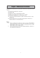
Chapter 5: Trouble Shooting Tips Chapter 5 Trouble Shooting Tips Star t up pr ob lems during assemb prob oblems assembll y After assembling the PC for the first time you may experience some start up problems. Before calling for technical support or returning for warranty, this chapter may help to address some of the common questions using some basic troubleshooting tips. a) System does not power up and the fans are not running. 1.
Motherboard User’s Guide c) The PC suddenly shuts down while booting up. 1. The CPU may experience overheating so it will shutdown to protect itself. Ensure the CPU fan is working properly. 2. From the BIOS setting, try to disable the Smartfan function to let the fan run at default speed. Doing a Load Optimised Default will also disable the Smartfan. Star t up pr ob lems after pr olong use prob oblems prolong After a prolong period of use your PC may experience start up problems again.
If fail, contact RMA CLR CMOS and restart. Yes Halt at POST screenΛ Yes Check if monitor has display Yes Check if Power Supply Unit (PSU) is working Power Bu on is pressed but PC fails to start. - need to CLRCMOS. HDD problem.