
User`s guide


16
Motherboard User’s Guide
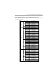
F_AUDIO: Front Panel Audio Header
This header allows the user to install auxiliary front-oriented microphone and
line-out ports for easier access.
Pin Signal Pin Signal
1 PORT1L 2 GND
3 PORT1 R 4 PRESENCE#
5 PORT2R 6 Sense1_return
7 SENS E_SEND 8 KEY
9 PORT2L 10 Sense2_return
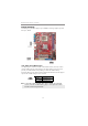
Pin Signal Pin Signal
1 USBPWR0 2 USBPWR1
3 USB_FP_P0(-) 4 USB_FP_P1(-)
5 USB_FP_P0(+) 6 USB_FP_P1(+)
7 GROUND 8 GROUND
9KEY 10NC
1. Locate the F_USB1~2 headers on the motherboard.
2. Plug the bracket cable onto the F_USB1~2 headers.
3. Remove a slot cover from one of the expansion slots on the system
chassis. Install an extension bracket in the opening. Secure the
extension bracket to the chassis with a screw.
F_USB1~2: Front panel USB Headers
The motherboard has four USB ports installed on the rear edge I/O port array.
Additionally, some computer cases have USB ports at the front of the case. If
you have this kind of case, use auxiliary USB headers F_USB1~2 to connect the
front-mounted ports to the motherboard.
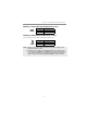
LPT: Onboard parallel port Header
This header allows the user to connect to the printer, scanner or devices.
Pin Signal Pin Signal
1STROBE 2 PD0
3 PD1 4 PD2
5 PD3 6 PD4
7 PD5 8 PD6
9PD7 10ACK
11 BUSK 12 PE
13 SLCT 14 ALF
15 ERROR 16 INIT
17 SLCTIN 18 Ground
19 Ground 20 Ground
21 Ground 22 Ground
23 Ground 24 Ground
25 Ground 26 Key