Motherboard User’s Guide This publication, including photographs, illustrations and software, is under the protection of international copyright laws, with all rights reserved. Neither this user’s guide, nor any of the material contained herein, may be reproduced without the express written consent of the manufacturer. The information in this document is subject to change without notice.
Motherboard User’s Guide Table of Contents Trademark ............................................................................................................ i Static Electricity Precautions ......................................................................................... i Pre-Installation Inspection ............................................................................................. i Chapter 1: Introduction ............................................................................
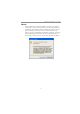
Motherboard User’s Guide Notice: 1 Owing to Microsoft’s certifying schedule is various to every supplier, we might have some drivers not certified yet by Microsoft. Therefore, it might happen under Windows XP that a dialogue box (shown as below) pop out warning you this software has not passed Windows Logo testing to verify its compatibility with Windows XP. Please rest assured that our RD department has already tested and verified these drivers.
Chapter 1: Introduction Chapter 1 Introduction This motherboard has a LGA775 socket for latest Intel® CoreTM 2 Quad*/ TM Core 2 Duo/Pentium® D*/Pentium® 4*/Celeron® D processors with Hyper-Threading Technology and Front-Side Bus (FSB) speeds up to 1066/ 800 MHz (Over spec up to 1333*). Hyper-Threading Technology, designed to take advantage of the multitasking features, giving you the power to do more things at once.
Motherboard User’s Guide Chipset The NVIDIA® MCP73V is a single-chip with proven reliability and performance. • • • • • • • • High Performance Host Interface: Supports Intel® CoreTM 2 Quad*/ TM Core 2 Duo/Pentium® D*/Pentium® 4*/Celeron® D processor family with over spec up to FSB1333* MHz Hyper-Threading Technology System Memory Controller Support: DDR2 SDRAM with up to maximum memory of 4 GB. PCI Express Graphics Interface Support: One PCI Express x16 port PCI Bus Interface Support: PCI Revision 2.
Chapter 1: Introduction Audio • • • • • 6 Channels of DAC support 16/20/24-bit PCM Format for 5.1 Audio Solution All ADCs support 48k/192k Independent Sample Rate Exceeds Microsoft PC2001 Requirement High Quality Differential CD input Power Support: Digital: 3.3V; Analog: 3.3V/5.0V LAN • • • • 10/100 Mb/s dual speed transceiver MII interface for external MAC devices 10/100 Mb/s IEEE 802.3 compliant IEEE 802.
Motherboard User’s Guide Package Contents Your motherboard package ships with the following items: The motherboard The User’s Guide One diskette drive ribbon cable (optional) One IDE drive ribbon cable The Software support CD Optional Accessories You can purchase the following optional accessories for this motherboard. The Extended USB module The CNR v.
Chapter 2: Motherboard Installation Chapter 2 Motherboard Installation To install this motherboard in a system, please follow these instructions in this chapter: Identify the motherboard components Install a CPU Install one or more system memory modules Make sure all jumpers and switches are set correctly Install this motherboard in a system chassis (case) Connect any extension brackets or cables to headers/connectors on the motherboard Install peripheral devices and make the appropriate conn
Motherboard User’s Guide Motherboard Components ITEM LABEL COMPONENTS ® LGA775 socket for Intel CoreT M2 Quad*/ CoreT M2 Duo/ 1 CPU Socket 2 CPU_FAN Pentium D*/Pentium 4*/Celeron D CPUs CPU cooling fan connector 3 DDR2_1~2 240-pin DDR2 SDRAM slots 4 ATX_POWER Standard 24-pin ATX pow er connector 5 SYS_FAN System cooling fan connector 6 SATA1~4 Serial ATA connectors 7 SPK Speaker header 8 LPT Onboard parallel port header ® ® ® 9 CLR_CMOS Clear CMOS jumper 10 F_PANEL Front
Chapter 2: Motherboard Installation I/O Ports The illustration below shows a side view of the built-in I/O ports on the motherboard. PS/2 Mouse Use the upper PS/2 port to connect a PS/2 pointing device. PS/2 Keyboard Use the low er PS/2 port to connect a PS/2 keyboard. COM Use the COM port to connect serial devices such as mice or fax/modems. COM is identified by the system as COM. VGA Port Use the VGA port to connect VGA devices.
Motherboard User’s Guide Installing the Processor This motherboard has a LGA775 socket for the latest Intel® CoreTM 2 Quad/ TM Core 2 Duo/Pentium® D/Pentium® 4/Celeron® D processors. When choosing a processor, consider the performance requirements of the system. Performance is based on the processor design, the clock speed and system bus frequency of the processor, and the quantity of internal cache memory and external cache memory.
Chapter 2: Motherboard Installation E. Close the load plate • Slightly push down the load plate onto the tongue side, and hook the lever. • CPU is locked completely. F. Apply thermal grease on top of the CPU. G. Fasten the cooling fan supporting base onto the CPU socket on the motherboard. H. Make sure the CPU fan is plugged to the CPU fan connector. Please refer to the CPU cooling fan user’s manual for mor detail installation procedure.
Motherboard User’s Guide Memory Module Installation Procedure These modules can be installed with up to 4 GB system memory. Refer to the following to install the memory module. 1. Push down the latches on both sides of the DIMM socket. 2. Align the memory module with the socket. There is a notch on the DIMM socket that you can install the DIMM module in the correct direction. Match the cutout on the DIMM module with the notch on the DIMM socket. 3.
Chapter 2: Motherboard Installation Table A: DDR2 (memory module) QVL (Qualified Vendor List) The following DDR2 800/667/533 memory modules have been tested and qualified for use with this motherboard. Type Size 512 MB DDR2 533 1 GB 256 MB 512 MB DDR2 667 1 GB 2 GB 512 MB DDR2 800 1 GB Vendor Module Name Aeneon AET660UD00-370A98Z Infineon HYS64T64400HU-3.7-A Kingston KVR533D2N4/512 PQI MEABR321LA01AA Samsung M378T6553BGO-CD 5 Infineon HYS64T128920HU-3.
Motherboard User’s Guide Jumper Settings Connecting two pins with a jumper cap is SHORT; removing a jumper cap from these pins, OPEN. CLR_CMOS: Clear CMOS Jumper Use this jumper to clear the contents of the CMOS memory. You may need to clear the CMOS memory if the settings in the Setup Utility are incorrect and prevent your motherboard from operating. To clear the CMOS memory, disconnect all the power cables from the motherboard and then move the jumper cap into the CLEAR setting for a few seconds.
Chapter 2: Motherboard Installation USBPWR_F: FRONT PANEL USB POWER SELECT Jumper 1 USBPWR_F Function VCC 5VSB Jum per Setting Short Pins 1-2 Short Pins 2-3 USBPWR_R: REAR USB PS/2 POWER SELECT Jumper Use this jumper to set the Rear USB PS/2 Power function. 1 USBPWR_R Function VCC 5VSB Jum per Setting Short Pins 1-2 Short Pins 2-3 Note:1. Make sure the power supply provides enough SB5V voltage before selecting the SB5V function. 2.
Motherboard User’s Guide Install the Motherboard Install the motherboard in a system chassis (case). The board is a Micro ATX size motherboard. You can install this motherboard in an ATX case. Make sure your case has an I/O cover plate matching the ports on this motherboard. Install the motherboard in a case. Follow the case manufacturer’s instructions to use the hardware and internal mounting points on the chassis.
Chapter 2: Motherboard Installation Connecting Optional Devices Refer to the following for information on connecting the motherboard’s optional devices: SPK: Speaker Header Connect the cable from the PC speaker to the SPK header on the motherboard.
Motherboard User’s Guide F_AUDIO: Front Panel Audio Header This header allows the user to install auxiliary front-oriented microphone and line-out ports for easier access. Pin 1 3 5 7 9 Signal PORT1L PORT1R PORT2R SENSE_SEND PORT2L Pin 2 4 6 8 10 Signal GND PRESENCE# Sense1_return KEY Sense2_return F_USB1~2: Front panel USB Headers The motherboard has four USB ports installed on the rear edge I/O port array. Additionally, some computer cases have USB ports at the front of the case.
Chapter 2: Motherboard Installation Install Other Devices Install and connect any other devices in the system following the steps below. Floppy Disk Drive The motherboard ships with a floppy disk drive cable that can support one or two drives. Drives can be 3.5" or 5.25" wide, with capacities of 360 K, 720 K, 1.2 MB, 1.44 MB, or 2.88 MB. Install your drives and connect power from the system power supply. Use the cable provided to connect the drives to the floppy disk drive connector FDD.
Motherboard User’s Guide Serial ATA Devices The Serial ATA (Advanced Technology Attachment) is the standard interface for the IDE hard drives, which is designed to overcome the design limitations while enabling the storage interface to scale with the growing media rate demands of PC platforms. It provides you a faster transfer rate of 3.0 Gb/s. If you have installed a Serial ATA hard drive, you can connect the Serial ATA cables to the Serial ATA hard drive or the connector on the motherboard.
Chapter 2: Motherboard Installation When you first start up your system, the BIOS should automatically detect your CD-ROM/DVD drive. If it doesn’t, enter the Setup Utility and configure the CD-ROM/DVD drive that you have installed. On the motherboard, locate the 4-pin header CD_IN. Pin 1 2 3 Signal CD Left Channel GND GND 4 CD Right Channel Expansion Slots This motherboard has one PCI Ex16, one PCI Ex1 and two 32-bit PCI slots.
Motherboard User’s Guide Follow the steps below to install an PCI Express/CNR/PCI expansion card. 1 Locate the PCI Express, CNR or PCI slots on the motherboard. 2 Remove the blanking plate of the slot from the system chassis. 3 Install the edge connector of the expansion card into the slot. Ensure the edge connector is correctly seated in the slot. 4 Secure the metal bracket of the card to the system chassis with a screw.
Chapter 3: BIOS Setup Utility Chapter 3 BIOS Setup Utility Introduction The BIOS Setup Utility records settings and information of your computer, such as date and time, the type of hardware installed, and various configuration settings. Your computer applies the information to initialize all the components when booting up and basic functions of coordination between system components. If the Setup Utility configuration is incorrect, it may cause the system to malfunction.
Motherboard User’s Guide Some options on the main menu page lead to tables of items with installed values that you can use cursor arrow keys to highlight one item, and press PgUp and PgDn keys to cycle through alternative values of that item. The other options on the main menu page lead to dialog boxes requiring your answer OK or Cancel by selecting the [OK] or [Cancel] key. If you have already changed the setup utility, press F10 to save those changes and exit the utility.
Chapter 3: BIOS Setup Utility f IDE Devices Your computer has one IDE channel which can be installed with one or two devices (Master and Slave). In addition, this motherboard supports two SATA channels and each channel allows one SATA device to be installed. Use these items to configure each device on the IDE channel. CMOS SETUP UTILITY – Copyright (C) 1985-2007, American Megatrends, Inc.
Motherboard User’s Guide Advanced Setup Page This page sets up more advanced information about your system. Handle this page with caution. Any changes can affect the operation of your computer. CMOS Setup Utility – Copyright (C) 1985-2007, American Megatrends, Inc.
Chapter 3: BIOS Setup Utility Boot Up NumLock Status This item determines if the NumLock key is active or inactive at system start-up time. APIC Mode This item allows you to enable or disable the APIC (Advanced Programmable Interrupt Controller) mode. APIC provides symmetric multi-processing (SMP) for systems, allowing support for up to 60 processors. 1st/2nd/3rd Boot Device Use these items to determine the device order the computer uses to look for an operating system to load at start-up time.
Motherboard User’s Guide Advanced Chipset Setup Page This page sets up more advanced chipset information about your system. Handle this page with caution. Any changes can affect the operation of your computer. CMOS Setup Utility – Copyright (C) 1985-2007, American Megatrends, Inc. Advanced Chipset Setup Help Item Memory Timings Top of Memory under 4GB Memory Remap Feature Auto 3.
Chapter 3: BIOS Setup Utility Integrated Peripherals Page This page sets up some parameters for peripheral devices connected to the system. CMOS Setup Utility – Copyright (C) 1985-2007, American Megatrends, Inc.
Motherboard User’s Guide Parallel Port Address Use this item to enable or disable the onboard Parallel port, and to assign a port address. Parallel Port Mode Use this item to select the parallel port mode. You can select Normal (Standard Parallel Port), ECP (Extended Capabilities Port), EPP (Enhanced Parallel Port), or BPP (Bi-Directional Parallel Port). ECP Mode DMA Channel Use this item to assign the DMA Channel under ECP Mode function. Parallel Port IRQ Use this item to assign IRQ to the parallel port.
Chapter 3: BIOS Setup Utility PWRON After PWR-Fail This item enables your computer to automatically restart or return to its operating status. Resume By PCI/PCI-E/Lan PME These items specify whether the system will be awakened from power saving modes when activity or input signal of the specified hardware peripheral or component is detected. Resume By USB(S3) This item allows you to enable/disable the USB device wakeup function from S3/S4 mode.
Motherboard User’s Guide Init Dispaly First This item allows you to choose the primary display card. Press to return to the main menu setting page. PCI Health Status Page This page helps you monitor the parameters for critical voltages, temperatures and fan speeds. CMOS Setup Utility – Copyright (C) 1985-2007, American Megatrends, Inc.
Chapter 3: BIOS Setup Utility Shutdown Temperature Enable you to set the maximum temperature the system can reach before powering down. System Component Characteristics These fields provide you with information about the system current operating status. • • • • • CPU Temperature System Temperature CPU Fan Speed CPU Vorce VDIMM Press to return to the main menu setting page. Frequency/Voltage Control Page This page helps you to set the clock speed and system bus for your system.
Motherboard User’s Guide CPU BSEL Select This item is used to select the CPU BSEL. PCIE Spread Spectrum If you enable spread spectrum, it can significantly reduce the EMI (ElectroMagnetic interface) generated by the PCIE. Memory Voltage This item allows users to adjust the DDR memory voltage. NB Voltage This item allows users to adjust the Northbridge voltage. Press to return to the main menu setting page.
Chapter 3: BIOS Setup Utility Change Supervisor Password You can select this option and press to access the sub menu. You can use the sub menu to change the supervisor password. Press to return to the main menu setting page. User Password Page This page helps you set up some parameters for the hardware monitoring function of this motherboard. CMOS Setup Utility – Copyright (C) 1985-2007, American Megatrends, Inc.
Motherboard User’s Guide Chapter 4 Software & Applications Introduction This chapter describes the contents of the support CD-ROM that comes with the motherboard package. The support CD-ROM contains all useful software, necessary drivers and utility programs to properly run our products. More program information is available in a README file, located in the same directory as the software. To run the support CD, simply insert the CD into your CD-ROM drive.
Chapter 4: Software & Applications The Exit button closes the Auto Setup window. To run the program again, reinsert the CD-ROM disc in the drive; or click the CD-ROM driver from the Windows Explorer, and click the Setup icon. The Application button brings up a software menu. It shows the bundled software that this mainboard supports. The ReadMe brings you to the Install Path where you can find out path names of software driver.
Motherboard User’s Guide 3 The support software will automatically install. Once any of the installation procedures start, software is automatically installed in sequence. You need to follow the onscreen instructions, confirm commands and allow the computer to restart as few times as needed to complete installing whatever software you selected. When the process is finished, all the support software will be installed and start working.
Chapter 4: Software & Applications Follow these instructions to Disable Vista UAC function: 1. Go to Control Panel. 2. Select Classic View. 3. Set User Account.
Motherboard User’s Guide 4. Select Turn User Account Control on or off and press Continue. 5. Disable User Account Control (UAC) to help protect your computer item and press OK, then press Restart Now. Then you can restart your computer and continue to install drivers without running blocked programs. Bundled Software Installation All bundled software available on the CD-ROM is for users’ convenience.