Motherboard User’s Guide This publication, including photographs, illustrations and software, is under the protection of international copyright laws, with all rights reserved. Neither this user’s guide, nor any of the material contained herein, may be reproduced without the express written consent of the manufacturer. The information in this document is subject to change without notice.
Motherboard User’s Guide Table of Contents Trademark ............................................................................................................ i Static Electricity Precautions ......................................................................................... i Pre-Installation Inspection ............................................................................................. i Chapter 1: Introduction ............................................................................
Motherboard User’s Guide Start up problems during assembly..........................................................40 Start up problems after prolong use........................................................41 Maintenance and care tips.....................................................................41 Notice: 1 Owing to Microsoft’s certifying schedule is various to every supplier, we might have some drivers not certified yet by Microsoft.
Chapter 1: Introduction Chapter 1 Introduction This motherboard has a LGA775 socket for latest Intel Core 2 Quad*/Intel® CoreTM 2 Duo/Pentium® Dual-Core/Celeron® Dual-Core/Celeron® 400 series processors with Front-Side Bus (FSB) speeds up to 1333/1066 MHz. It integrates Intel®G41 Northbridge and ICH7 Southbridge that supports the Serial ATA interface for high-performance and mainstream desktop PCs. The memory controller supports DDR3 memory DIMM frequencies of 1066/800.
Motherboard User’s Guide Chipset The Intel® G41 Northbridge (NB) and Intel® ICH7 Southbridge (SB) chipsets are based on an innovative and scalable architecture with proven reliability and performance. • High Performance Host Interface: Supports Intel Core 2 Quad /Intel® CoreTM 2 Duo/Pentium® Dual-Core/Celeron® Dual-Core/Celeron® 400 series processors family with FSB1333/1066 MHz • System Memory Controller Support: DDR3 SDRAM with up to maximum memory of 4 GB.
Chapter 1: Introduction Audio • • • • 5.1 Channel High Definition Audio Codec Exceeds Microsoft Windows Logo Program (WLP) Requirements ADCs support 44.1K/48K/96K/192KHz sample rate Power Support: Digital: 3.3V; Analog: 5.0V Onboard LAN (optional) • • • • • • Supports PCI ExpressTM 1.1 Integrated 10/100/1000 transceiver Wake-On-LAN (WOL) and remote wake-up support Supports PCI ExpressTM 1.
Motherboard User’s Guide Package Contents Your motherboard package ships with the following items: The motherboard The User’s Guide Two Serial ATA cables Optional Accessories You can purchase the following optional accessories for this motherboard. The Extended USB module The IDE drive ribbon cable The Serial ATA power cable Note: You can purchase your own optional accessories from the third party, but please contact your local vendor on any issues of the specification and compatibility.
Chapter 2: Motherboard Installation Chapter 2 Motherboard Installation To install this motherboard in a system, please follow these instructions in this chapter: Identify the motherboard components Install a CPU Install one or more system memory modules Make sure all jumpers and switches are set correctly Install this motherboard in a system chassis (case) Connect any extension brackets or cables to headers/connectors on the motherboard Install peripheral devices and make the appropriate conn
Motherboard User’s Guide Motherboard Components LABEL COMPONENTS LGA775 socket for Intel Core 2 Quad/Intel® CoreTM 2 Duo/ Pentium® Dual-Core/Celeron® Dual-Core/Celeron® 400 series processors 2. CPU_FAN CPU cooling fan connector 3. DDR3_1~2 240-pin DDR3 SDRAM slots 4. ATX_POWER Standard 24-pin ATX power connector 5. IDE Primary IDE channel 6. SPK Speaker header 7. CLR_CMOS Clear CMOS jumper 8. SATA1~2 Serial ATA connectors 9. F_USB1~2 Front panel USB headers 10.
Chapter 2: Motherboard Installation I/O Ports The illustration below shows a side view of the built-in I/O ports on the motherboard. PS/2 Mouse Use the upper PS/2 port to connect a PS/2 pointing device. PS/2 Keyboard Use the low er PS/2 port to connect a PS/2 keyboard. VGA Port Use the VGA port to connect VGA devices. LAN Port Connect an RJ-45 jack to the LAN port to connect your computer to the Netw ork. USB Ports Use the USB ports to connect USB devices.
Motherboard User’s Guide Installing the Processor This motherboard has a LGA775 socket for the latest Intel Core 2 Quad/Intel® CoreTM 2 Duo/Pentium® Dual-Core/Celeron® Dual-Core/Celeron® 400 series processors. When choosing a processor, consider the performance requirements of the system. Performance is based on the processor design, the clock speed and system bus frequency of the processor, and the quantity of internal cache memory and external cache memory.
Chapter 2: Motherboard Installation E. Close the load plate • Slightly push down the load plate onto the tongue side, and hook the lever. • CPU is locked completely. F. Apply thermal grease on top of the CPU. G. Fasten the cooling fan supporting base onto the CPU socket on the motherboard. H. Make sure the CPU fan is plugged to the CPU fan connector. Please refer to the CPU cooling fan user’s manual for mor detail installation procedure.
Motherboard User’s Guide Memory Module Installation Procedure These modules can be installed with up to 4 GB system memory. Refer to the following to install the memory module. 1. Push down the latches on both sides of the DIMM socket. 2. Align the memory module with the socket. There is a notch on the DIMM socket that you can install the DIMM module in the correct direction. Match the cutout on the DIMM module with the notch on the DIMM socket. 3.
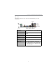
Chapter 2: Motherboard Installation Table A: DDR3 (memory module) QVL (Qualified Vendor List) The following DDR3 1333/1066memory modules have been tested and qualified for use with this motherboard.
Motherboard User’s Guide Type Size 1 GB Vendor Module Name A-data AD3U1333B1G9-B Hynix HMT112U6AFP8C-H9N0 AA KingMax FLFD45F-B8KG9 NAES Kingston KVR1333D3N9/1G MT8JTF12864AY-1G4D1 Micron MT8JTF12864AZ-1G4F1 PSC AL7F8G73D-DG1 Ramaxel RMR1810KD48E7F-1333 M378B2873DZ1-CH9 Samsung DDR3 1333 2 GB M378B2873EH1-CH9 Silicon Pow er SP001GBLTU133S01 A-data AD3U1333B2G9-B Apacer 78.A1GC6.9L1 Elixir M2F2G64CB8HA4N-CG 0903.
Chapter 2: Motherboard Installation Jumper Settings Connecting two pins with a jumper cap is SHORT; removing a jumper cap from these pins, OPEN. CLR_CMOS: Clear CMOS Jumper Use this jumper to clear the contents of the CMOS memory. You may need to clear the CMOS memory if the settings in the Setup Utility are incorrect and prevent your motherboard from operating.
Motherboard User’s Guide USBPWR_F: FRONT PANEL USB POWER SELECT Jumper 1 USBPWR_F Function VCC 5VSB Jum per Setting Short Pins 1-2 Short Pins 2-3 USBPWR_R: REAR USB PS/2 POWER SELECT Jumper Use this jumper to set the Rear USB PS/2 Power function. 1 USBPWR_R Function VCC 5VSB Jum per Setting Short Pins 1-2 Short Pins 2-3 Note:1. Make sure the power supply provides enough SB5V voltage before selecting the SB5V function. 2.
Chapter 2: Motherboard Installation Install the Motherboard Install the motherboard in a system chassis (case). The board is a Micro ATX size motherboard. You can install this motherboard in an ATX case. Make sure your case has an I/O cover plate matching the ports on this motherboard. Install the motherboard in a case. Follow the case manufacturer’s instructions to use the hardware and internal mounting points on the chassis.
Motherboard User’s Guide Connecting Optional Devices Refer to the following for information on connecting the motherboard’s optional devices: SPK: Speaker Header Connect the cable from the PC speaker to the SPK header on the motherboard.
Chapter 2: Motherboard Installation COM: Onboard Serial Port Header Connect a serial port extension bracket to this header to add a second serial port to your system. Pin 1 3 5 7 9 Signal DCDB SOUTB GND RTSB RI Pin 2 4 6 8 10 Signal SINB DTRB DSRB CTSB KEY F_AUDIO: Front Panel Audio Header This header allows the user to install auxiliary front-oriented microphone and lineout ports for easier access.
Motherboard User’s Guide LPT: Onboard Parallel Port Header This header allows the user to connect to the printer, scanner or devices.
Chapter 2: Motherboard Installation The motherboard ships with an IDE cable that can support one or two IDE devices. If you connect two devices to a single cable, you must configure one of the drives as Master and one of the drives as Slave. The documentation of the IDE device will tell you how to configure the device as a Master or Slave device. The Master device connects to the end of the cable. Install the device(s) and connect power from the system power supply.
Motherboard User’s Guide Follow the steps below to install an PCI Express/CNR/PCI expansion card. 1 Locate the PCI Express, CNR or PCI slots on the motherboard. 2 Remove the blanking plate of the slot from the system chassis. 3 Install the edge connector of the expansion card into the slot. Ensure the edge connector is correctly seated in the slot. 4 Secure the metal bracket of the card to the system chassis with a screw.
Chapter 3: BIOS Setup Utility Chapter 3 BIOS Setup Utility Introduction The BIOS Setup Utility records settings and information of your computer, such as date and time, the type of hardware installed, and various configuration settings. Your computer applies the information to initialize all the components when booting up and basic functions of coordination between system components. If the Setup Utility configuration is incorrect, it may cause the system to malfunction.
Motherboard User’s Guide Some options on the main menu page lead to tables of items with installed values that you can use cursor arrow keys to highlight one item, and press PgUp and PgDn keys to cycle through alternative values of that item. The other options on the main menu page lead to dialog boxes requiring your answer OK or Cancel by selecting the [OK] or [Cancel] key. If you have already changed the setup utility, press F10 to save those changes and exit the utility.
Chapter 3: BIOS Setup Utility IDE BusMaster This item enables or disables the DMA under DOS mode. We recommend you to leave this item at the default value. f IDE Devices Your computer has one IDE channel which can be installed with one or two devices (Master and Slave). In addition, this motherboard supports two SATA channels and each channel allows one SATA device to be installed. Use these items to configure each device on the IDE channel.
Motherboard User’s Guide Advanced Setup Page This page sets up more advanced information about your system. Handle this page with caution. Any changes can affect the operation of your computer. CMOS Setup Utility – Copyright (C) 1985-2005, American Megatrends, Inc.
Chapter 3: BIOS Setup Utility APIC Mode This item allows you to enable or disable the APIC (Advanced Programmable Interrupt Controller) mode. APIC provides symmetric multi-processing (SMP) for systems, allowing support for up to 60 processors. 1st/2nd/3rd Boot Device Use these items to determine the device order the computer uses to look for an operating system to load at start-up time.
Motherboard User’s Guide Press to return to the main menu page. Advanced Chipset Setup Page This page sets up more advanced chipset information about your system. Handle this page with caution. Any changes can affect the operation of your computer. CMOS Setup Utility – Copyright (C) 1985-2005, American Megatrends, Inc.
Chapter 3: BIOS Setup Utility Integrated Peripherals Page This page sets up some parameters for peripheral devices connected to the system. CMOS Setup Utility – Copyright (C) 1985-2005, American Megatrends, Inc.
Motherboard User’s Guide Parallel Port IRQ Use this item to assign IRQ to the parallel port. USB Functions Use this item to enable or disable the USB function. Legacy USB Support Use this item to enable or disable support for legacy USB devices. Setting to Auto allows the system to detect the presence of USB device at startup. If detected, the USB controller legacy mode is enabled. If no USB device is detected, the legacy USB support is disabled. Press to return to the main menu setting page.
Chapter 3: BIOS Setup Utility Resume By PCI/PCI-E/Lan PME These items specify whether the system will be awakened from power saving modes when activity or input signal of the specified hardware peripheral or component is detected. Resume By PS2 KB (S3) This item enable or disable you to allow keyboard activity to awaken the system from power saving mode. Resume By PS2 MS (S3) This item enable or disable you to allow mouse activity to awaken the system from power saving mode.
Motherboard User’s Guide PCI Health Status Page This page helps you monitor the parameters for critical voltages, temperatures and fan speeds. CMOS Setup Utility – Copyright (C) 1985-2005, American Megatrends, Inc. PC Health Status Help Item -=- System Hardware Monitor-=Smart Fan Function Press Enter CPU Fan Speed : 1134 RPM CPU Vcore : 1.216 V VDIMM : 1.472 V Case Open Warning Disabled Chassis Opened No -=- PECI Mode-=Offset to TCC Activation Temp.
Chapter 3: BIOS Setup Utility CMOS Setup Utility - Copyright (C) 1985-2005, American Megatrends, Inc. Smart Fan Function Help Item Smart Fan Function SMART Fan Mode SMART Fan start PWM value CPU DeltaT SMART Fan start Offset (-) Fan1 Slope PWM value/1 Unite Fan1 Full Speed Offset(-) Enabled Normal 28 +3 32 5 7 Options Normal: auto adjusts depending on the CPU temperature. Quiet: auto minimizes fan speed for quiet environment operation. Silent: auto restricts fan speed to make system more quietly.
Motherboard User’s Guide CMOS Setup Utility - Copyright (C) 1985-2005, American Megatrends, Inc. Smart Fan Function Help Item Smart Fan Function SMART Fan Mode SMART Fan start PWM value CPU DeltaT SMART Fan start Offset (-) Fan1 Slope PWM value/1 Unite Fan1 Full Speed Offset(-) Enabled Quiet 28 +3 32 5 7 Options Normal: auto adjusts depending on the CPU temperature. Quiet: auto minimizes fan speed for quiet environment operation. Silent: auto restricts fan speed to make system more quietly.
Chapter 3: BIOS Setup Utility CMOS Setup Utility - Copyright (C) 1985-2005, American Megatrends, Inc. Smart Fan Function Help Item Smart Fan Function SMART Fan Mode SMART Fan start PWM value CPU DeltaT SMART Fan start Offset (-) Fan1 Slope PWM value/1 Unite Fan1 Full Speed Offset(-) Enabled Manual 28 +3 32 5 7 Options Normal: auto adjusts depending on the CPU temperature. Quiet: auto minimizes fan speed for quiet environment operation. Silent: auto restricts fan speed to make system more quietly.
Motherboard User’s Guide Shutdown Temperature Enable you to set the maximum temperature the system can reach before powering down. System Component Characteristics These items display the monitoring of the overall inboard hardware health events, such as System & CPU temperature, CPU & DIMM voltage, CPU & system fan speed,...etc.
Chapter 3: BIOS Setup Utility CPU Frequency This item indicates the current CPU frequency. Users can not make any change to this item. Please noted that the frequency will be varied with different CPU. CPU Frequency Setting (333MHz) This item is used to set the CPU Frequency. Auto Detect DIMM/PCI Clk (Enabled) When this item is enabled, BIOS will disable the clock signal of free DIMM/PCI slots.
Motherboard User’s Guide User Password Page This page helps you set up some parameters for the hardware monitoring function of this motherboard. CMOS Setup Utility – Copyright (C) 1985-2005, American Megatrends, Inc. User Password User Password : Not Installed Change User Password Help Item Press Enter : Move Enter: Select +/-/: Value F10: Save Esc: Exit F1: General Help F9: Load Default Settings User Password (Not Installed) This item indicates whether a user password has been set.
Chapter 4: Software & Applications Chapter 4 Software & Applications Introduction This chapter describes the contents of the support DVD-ROM/CD-ROM that comes with the motherboard package. The support DVD-ROM/CD-ROM contains all useful software, necessary drivers and utility programs to properly run our products. More program information is available in a README file, located in the same directory as the software. To run the support disk, simply insert the disk into your DVD-ROM/CD-ROM drive.
Motherboard User’s Guide The Browse CD button is a standard Windows command that you can check the contents of the disc with the Windows file browsing interface. The Exit button closes the Auto Setup window. To run the program again, reinsert the DVD-ROM/CD-ROM disc in the drive; or click the DVD-ROM/CD-ROM driver from the Windows Explorer, and click the Setup icon. The Utilities button brings up a software menu. It shows the bundled software that this mainboard supports.
Chapter 4: Software & Applications 3 The support software will automatically install. Once any of the installation procedures start, software is automatically installed in sequence. You need to follow the onscreen instructions, confirm commands and allow the computer to restart as few times as needed to complete installing whatever software you selected. When the process is finished, all the support software will be installed and start working.
Motherboard User’s Guide Chapter 5 Trouble Shooting Tips Star t up pr ob lems during assemb prob oblems assembll y After assembling the PC for the first time you may experience some start up problems. Before calling for technical support or returning for warranty, this chapter may help to address some of the common questions using some basic troubleshooting tips. a) System does not power up and the fans are not running. 1.
Chapter 6: Trouble Shooting Tips c) The PC suddenly shuts down while booting up. 1. The CPU may experience overheating so it will shutdown to protect itself. Ensure the CPU fan is working properly. 2. From the BIOS setting, try to disable the Smartfan function to let the fan run at default speed. Doing a Load Optimised Default will also disable the Smartfan. Star t up pr ob lems after pr olong use prob oblems prolong After a prolong period of use your PC may experience start up problems again.
If fail, contact RMA CLR CMOS and restart. Yes Halt at POST screen? Yes Check if monitor has display Yes Check if Power Supply Unit (PSU) is working Power Bu on is pressed but PC fails to start. CMOS setup error, - need to CLRCMOS. HDD problem.