
Installation guide


C99015
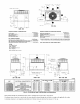
MAXIMUM WEIGHT A B
SIZE
I kg in. I mm I mm
JNIT PYIP
018 271 123.2 20.0 508.0 14.0 355.6
024 302 137.3 22.5 571.5 13.0 330.2
030 302 137.3 21.5 546.1 13.75 349.3
036 342 155.1 22.5 571.5 14.0 355.6
042 377 171.4 21.5 546.1 13.5 342.9
048 437 198.6 22.0 558.5 17.0 432.0
060 472 214.5 22.0 558.5 17.0 432.0
INIT PY2P
024 312 142 22.0 558.5 14.50 368.3
030 335 152 22.0 558.5 15.30 388.6
036 343 156 22.0 558.5 15.30 388.6
042 404 183 23.0 584.2 16.3 414.0
048 443 201 21.5 546.1 16.3 414.0
060 490 222 23.5 596.9 16.3 414.3
PROCEDURE 5--RIG AND PLACE UNIT Fig. 7B--Suggested Rigging
CAUTION: When installing the unit on a rooftop, be sure the roof will support the additional weight.
Use spreader bars or crate top when rigging the unit. The units must be rigged for lifting (See Fig. 6). Refer to Table 1 and 2 for operating weight.
Use extreme caution to prevent damage when moving the unit. Unit must remain in an upright position during all rigging and moving
operations.The unit must be level within I/4" for proper condensate drainage; therefore, the ground-level pad or accessory roof curb must be level
before setting the unit in place. When a field-fabricated support is used, be sure that the support is level and properly supports the unit. Lifting
point should be directly over the center of gravity for the unit.
PROCEDURE 6--CONNECT CONDENSATE DRAIN
NOTE: When installing condensate drain connection be sure to comply with local codes and restrictions,
Models PYIP and PY2P dispose of condensate water through a 3/4 in. NPT fitting which exits through the compressor access panel (See Fig. 2
and 3 for location).
Condensate water can be drained directly onto the roof in rooftop installations (where permitted) or onto a gravel apron in ground-level
installations. Install a field-supplied condensate trap at end of condensate connection to ensure proper drainage. Make sure that the outlet of the
trap is at least 1 in. lower than the drain pan condensate connection to prevent the pan from overflowing (See Fig. 8). Prime the trap with water.
When using a gravel apron, make sure it slopes away from the unit,
if the installation requires draining the condensate water away from the unit, install a 2-in. trap at the condensate connection to ensure proper
drainage (See Fig. 8). Make sure that the outlet of the trap is at least I in. lower than the drainpan condensate connection. This prevents the pan
fi'om overflowing.
Prime the trap with water, Connect a drain tube - using a minimum of 3/4-in. PVC or 3/4-in. copper pipe (all field-supplied) - at the outlet end
of the 2-in. trap. Do not undersize the tube. Pitch the drain tube downward at a slope of at least 1-in. for every 10 fl of horizontal run. Be sure
to check the drain tube for leaks.
PROCEDURE 7--INSTALL FLUE HOOD
The flue hood assembly is shipped screwed to the coil panel in the indoor blower compartment. Remove the service access panel to locate the
assembly (See Fig. 31).
NOTE: Dedicated low NO× models MUST be installed in California Air Quality Management Districts where a Low NO× rule exists.
These models meet the California maximum oxides of nitrogen (NO×) emissions requirements of 40 nanograms/joule or less as shipped from the
factory.
NOTE: Low NO× requirements apply only to natural gas installations.
A CAUTION: The venting system is designed to ensure proper venting. The flue hood assembly must be installed as
indicated in this section of the unit installation instructions.