
Installation guide


These instructions cover minimum requirements and conform to existing national standards and safety codes. In some instances, these instructions
exceed certain local codes and ordinances, especially those that may not have kept up with changing residential construction practices. We require
these instructions as a minimum for a safe installation.
INTRODUCTION
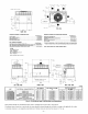
The PYIP and PY2P units (See Fig. I) are fully self-contained, combination Category 1gas heating/electric cooling units designed for outdoor
installation (See Fig. 2 and 3 for unit dimensions). All unit sizes have return and discharge openings for both horizontal and downflow
configurations, and are factory shipped with all downflow duct openings covered. Units may be installed either on a rooftop, a cement slab, or
directly on the grounst if local codes permit (See Fig. 4 for roof curb dimensions).
Models with an N in the thirteenth position of the model number are dedicated Low NO×units designed for California installations.
These models meet the California maximum oxides of nitrogen (NOx) emissions requirements of 40 nanograms/joule or less as shipped from the
factory and must be installed in California Air Quality Management Districts where a Low NO× rule exists.
RECEIVING AND INSTALLATION
PROCEDURE I--CHECK EQUIPMENT
A. IDENTIFY UNIT
The unit model number and serial number are stamped on unit identification plate. Check this information against shipping papers and job data.
Verify unit voltage and amperage requirements listed on unit rating plate agree with power supply provided to unit.
B. INSPECT SHIPMENT
inspect for shipping damage while Emitis still on shipping pallet. If unit appears to be damaged or is torn loose from its anchorage, have it examined
by transportation inspectors before removal. Forward claim papers directly to transportation company. Manufacturer is not responsible for any
damage incurred in transit.
Check all items against shipping list. immediately notify the nearest distributor if any item is missing.
To prevent loss or damage, leave all parts in original packages until installation.
C. INSTALLATION
1. Remove unit from shipping carton. Leave top shipping skid on the unit as a spreader bar to prevent the rigging straps from damaging the
unit. if the wood skid is not available, use a spreader bar of sufficient length to protect unit from damage.
2. Position the lifting bracket assembly around the base of the unit. Be sure the strap does not twist.
3. Place each of the 4 metal lifting brackets into the rigging holds in the composite pan.
4. Thread lifting bracket strapping around bottom perimeter of unit as follows:
a. Open lever of tension buckle (ratchet type).
b. Feed strapping through tension buckle as shown in Fig. 7A.
c. Pull strapping through tension buckle unit taut.
d. Snap lever down to lock strap in tension buckle. To release strapping, squeeze safety latch, lift lever, and pull webbing outward.
5. Tighten the tension buckle until it is taut. Lifting brackets must be secure in the rigging holds.
6. Attach field-supplied clevis or hook of sufficient strength to hole in the lifting bracket (See Fig. 7B).
7. Attach the 2 safety straps directly to the clevis or hook at the 4 rigging brackets. DO NOT attach the safety straps to the
lifting brackets (See Fig. 7B).
8. Position lifting point directly over the unit's center of gravity.
9. Lift unit. When unit is directly over the roof curb, remove the 2 safety straps. Lower the equipment onto the roof curb.
PROCEDURE 2--PROVIDE UNIT SUPPORT
A. ROOFCURB
install accessory roof curb in accordance with instructions shipped with curb (See Fig. 4 for roof curb dimensions), install insulation, cant strips,
roofing, and flashing. Ductwork must be attached to curb.
IMPORTANT: The gasketing of the unit to the roof curb is critical for a watertight seal. Install gasketing material supplied with the roof curb.
improperly applied gasketing can also result in air leaks and poor unit performance.
Curb should be level to within 1/4 in. This is necessary for unit drain to function properly. Refer to accessory roof curb installation instructions
for additional information as required.
B. SLAB MOUNT
Place the unit on a solid, level concrete pad that is a minimum of 4 in. thick with 2 in. above grade. The slab should be flush on the compressor
end of the unit (to allow condensate drain installation) and should extend 2 in. on the three remaining sides of the unit (See Fig. 6). Do not secure
the unit to the slab except when required by local codes.
C. GROUND MOUNT
The unit may be installed either on a slab or placed directly on the ground if local codes permit. Place the unit on level ground prepared with gravel
for condensate discharge.
PROCEDURE 3--FIELD FABRICATE DUCTWORK
Secure all ducts to roof curb and building structure on vertical discharge units. Do not connect ductwork to unit. For horizontal applications, unit
is provided with flanges on the horizontal openings. Installation of flexible duct connector is recommensted to prevent transmission of vibration
and/or noise to structure. All ductwork should be secured to the flanges, insulate and weatherproof all external ductwork, joints, and roof openings
with counter flashing and mastic in accordance with applicable codes.
.... 3___