
User guide

INS-006 Date code: 201200
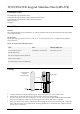
Wiring
TOUCHLOCK keypads are supplied with 3m of cable. The colours of the cable cores correspond to the
labelling on the Switch2/Net2 ACU.
To save space on the board, a keypad wired to the Net2 ACU shares power and LED terminals with the
reader.
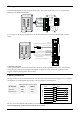
Connecting 2 keypads
If 2 keypads are to be connected to Switch2 they should be wired in parallel but the Yellow wire from the
second keypad connects into the Mauve terminal. If 2 keypads are to be connected to Net2 the second
keypad connects to the keypad 2 slot provided.
Cable Extensions
The type of cable used to extend this distance will effect the maximum distance the keypad can be extended.
All distances are assuming that the keypad is wired according to our instructions.
Maximum distance from ACU
ACU used
CR9538 CR9540
Net2 ACU 30M 30M
Switch2 ACU 30M 30M
Be sure, when extending the cable distance beyond 3M, to keep the colours the same throughout the run.
Beyond 10M pull up resistors must be fitted as shown above!
Red(5v)
Brown
Orange
Green
Yellow
* Yellow
Black
Control
unit
Inputs
Attach
Q.C. Label
here
Red
Brown
Orange
Green
Yellow
Blue
Mauve
Exit
Contact
Black
Card reader or keypad
12v
0v
N.C.
N.O.
Com
Bell
PowerDoor relay
Alarm
witch
2
S
Brown
Orange
Yellow
Green
Red
Black & White
Purple
Brown
Orange
Yellow
Green
Red & Blue
Black & White
Purple
Blue
Not connected
From Keypad
To control unit
Junction
box
Keypad 2
Yellow
Orange
Screen
White/Orange
Orange
Green
White/Green
Reader 1 Keypad 1
Brown
Yellow
Orange
Red
Brown
Orange
Green
Yellow
Blue
Mauve
Blk/Wht
Tx
Rx
Red (5V)
Green (green LED)
Blk/Wht (0V)
Brown (load)
Yellow (data)
Orange (clock)
*
* 220 Ohm resistor
supplied in the keypad fitting kit
CAT5 cable colours
5
4
3
2
1
Network