
User Manual

10V DC 14V DC
140 mA
125 kHz
600 µs
-20 °C +55 °C
IPX7
P200 80 mm 50 mm
2500 mm
80 mm 50 mm
2000 mm
P200 200 mm 200 mm
18 mm
205 mm 205 mm
42 mm
Voltage
Clock and data bit period
Carrier frequency
Specications
Operating temperatures - all items
Electrical
Environment
Dimensions
Min
Max
Width
Height
Depth
Current
1 - Readers/Keypads not working.
Q- Software settings - Conrm that the settings of the reader or keypad are correct.
Q- Connections - Check the wiring and integrity of the connectors. If possible, test this reader on the other port.
Q- Cable - Belden 9540 should be used to extend the reader cable (100 m maximum). Twisted pair alarm cable
Q should not be used. To conrm that an extended reader cable is not faulty, wire the reader directly to the port.
Q- Supply voltage - Conrm that the voltage is within specication. (see table)
Q- User token - Conrm that the user token used for testing is OK by presenting it to a known working reader.
Q- Interference - Conrm whether the reader works when tested 'in hand' and not mounted on the wall.
Q Ensure PROXIMITY readers are not mounted back to back and there is no interference from other RF devices.
2 - Readers / Keypads - Extending cable.
QOnly Belden CR9538 / 9540 can be used for cable extensions. CR9538 8 core up to 25 m, CR9540 10 core
Qup to 100 m (maximum). With CR9540, the two additional cores should be used to double up the power.
3 - Net2. What to do if a user has no access - Check the reader LED's when a card is shown.
Q- No LED's - the reader has no power.
Q- No change in display - try the card on a known working reader. If there is still no response, replace the card.
Q- Green LED ashing when a card is presented; check relay 1 LED to check for activity and also the lock wiring.
Q- Red LED is ashing when a card is presented; check the validity of the user at the PC.
Q Check user's access level and ensure they should have access by clicking on Current Validity.
Q Check the 'Valid Until' date and conrm this has not expired.
Q- Reinstate the ACU from the doors screen. Select the ACU's you wish to reinstate and then click OK.
4 - Switch2 - Adding an additional card pack.
QYou need to be in possession of the original enrolment card. Present the original enrolment card to the reader
Qand the Amber LED will ash, Green & Red LED's will be off, then present the Enrolment card from the new
Qcard pack; the reader will beep and all LED's will be lit. The additional cards will now be valid. Repeat this with
Qeach reader and with any additional card packs. Any valid enrolment card can be used to add further packs.
QThis is the same for enrolling function card packs onto a system.
5 - Switch2 - How to reset the controller.
Q1. Disconnect the power and remove the wires from the Green and Mauve terminals.
Q2. Insert a wire link between the Green and Mauve terminals.
Q3. Reconnect the power (the unit will beep 4 times).
Q4. Disconnect the power and remove the link wire, reconnect the Green and Mauve wires.
Q5. Reconnect the power (the unit will beep 3 times per second). The unit is ready to be enrolled.
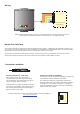
Here is the list of topics about this product that receive the most technical support enquiries.
We list them here to help you speed up the installation and trouble shooting process.
Technical Help
The declaration of conformity is available on request. Contact details are provided at: http://paxton.info/596
Paxton Access Ltd hereby declares that this product is in conformity with all the essential requirements of Directive
1999/5/EC. This equipment is intended for use in all EU and EFTA countries and all other countries worldwide.
Max
Min
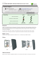
P200E (metal mount)
P200E (metal mount)
Read Range
Token
Keyfob
Hands Free Token
Waterproof
Outdoor Use
This product is not suitable for retail sale. All warranties are invalid if this product is not installed by a competent person.