
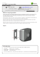
Specifications

2 t e N C o n t r t i n U l o
G r D E L n e e
E / t i x E n t r y
V 0
V 2 1
Net2 A ir I n t e r fa c e
R r e d a e
Not C onne c t ed
Not C onne c t ed
Not C onne c t ed
12V 7Ah
V 2 1
V 0
V 2 1
V 0
V 2 1
V 0
U S P
V 0
INPUT A C 100-240V
50 / 60 Hz
1.2A
OUTPUT DC 13.8V 2A
Sealed Rechargeable
Battery
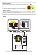
A seperate power supply must be
connected here for the reader to
function
Blue/Clock/D1
Yellow/Data/D0
Red/Interface On
Green/Green LED
Orange/Interface Comms
Brown/Red LED
12V
0V
Mauve/Not Used
Black/0V
Not Connected
Blue/Clock/D1
Yellow/Data/D0
Red/Interface On
Green/Green LED
Orange/Interface Comms
Brown/Red LED
12V
0V
Test Jumper and Connector
Test Purposes only - Not required during Installation
Mauve/Not Used
Black/0V
Not Connected
Blue/Clock/D1
Yellow/Data/D0
Red/Interface On
Green/Green LED
Orange/Interface Comms
Brown/Red LED
12V
0V
Mauve/Not Used
Black/0V
Not Connected
Blue/Clock/D1
Yellow/Data/D0
Red/Interface On
Green/Green LED
Orange/Interface Comms
Brown/Red LED
12V
0V
Test Jumper and Connector
Test Purposes only - Not required during Installation
Mauve/Not Used
Black/0V
Not Connected
1
Screen or spare cores from
network cable
3
4
KR 1 redae dapye 1
R le a y 2 R le a y 1
Keypad 2 Reader 2
stupnI P ewo r
CA nidoc elbac 5T g
krowteN
Net2 classic
2
R
cd V21 de
R DEL de
DEL rebm
A
DEL neerG
0D/ataD
1D/kcolC
tceteD
aideM
tuo V0
daoL
ataD
kcolC
T
F
:noituaC ro ylno sredaer c.d V21 . F tcerroc ro
noitcennoc fo fe
r sredaer V5 dlo r
e ot
snoitcurtsni
http://paxton.info/107
123456
0889
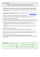
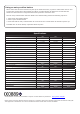
Wiring
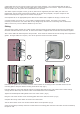
Read in, read out
When using in and out readers, users may be picked up by both readers as they move through the door which
will reduce the reliability of any roll call or anti-passback application. Ensure that sufcient spacing is provided
between these readers for optimum range and reliability.
Positioning readers
Hands free readers should be positioned so that their transmission elds do not overlap.
(see table on back page for typical hands free ranges)
For optimum keyfob battery life please choose your reader location carefully to
avoid placing it within hands free range of work stations, rest or smoking areas.
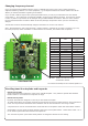
You will see that the interface is mounted upside down in the housing.
This is to position the internal aerial away from other reader components and is intentional.
Interface Module Reader Module