
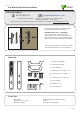
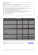
Specifications

Page 2
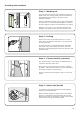
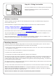
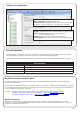
The lock case and cylinder (not supplied) must rst be
tted to the door, ensuring that a 22-24 mm diameter
hole is drilled for the follower (As shown on the
template provided).
Slide the spindle through the lock to allow the template
to locate over it. Ensure that the template is square to
the door edge by using the top and bottom ruler scales.
Mark the 2 x 10 mm, 1 x 16 mm holes. Remove the
template and repeat the procedure for the other side.
Installing the hardware
Step 1 - Marking out
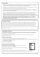
Step 2 - Drilling
Remove the lock if required and drill the 2 x 10 mm
holes for the mounting screws and 1 x 16 mm hole for
the wiring harness.
To ensure accuracy you should drill these holes from
both sides of the door towards the centre. This also
avoids the risk of damaging the door face when the drill
breaks through.
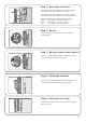
Step 3 - Contact switch (optional)
If a contact switch is to be tted, an additional hole is
required in the edge of the door.
Drill a hole of the required size to receive the switch
assembly. This should intersect the 16 mm hole drilled
previously to take the wiring harness.
Feed the contact wires through the door to exit on the
inside.
Ø 16
37
105
Ø 10
Paxton
70
60
50
40
30
10
5
5
15
15
0
20
25
25
35
35
45
55
65
75
45
55
65
75
10
20
30
40
60
70
50
The spindle is locked into the front lock assembly by
means of a spring loaded pin.
Ensure that the spindle pin and the hole in the square
drive are in alignment before depressing the pin and
sliding the bar into the assembly. The pin will then latch
into the hole securing the spindle in place.
Step 4 - Attach the Spindle