
Unit installation

Page 1
redaeR
:n oitu
a
C yl
nos
redaerC D V21roF
12V
Red LED
Amber LED
Green LED
Data/D0
Clock/D1
Media Detect
0V
Entry
12V
12V Lock
0V
0V
N.C.
N.O.
COM
Alarm
12V
Green LED
Exit
0V
Contact
0V
0V
Tamper
PSU
0V
nott
u Btix
E
yaleR
kcoL
stuptuO
stupnI
rewoP
tcatnoC
repmaT/USP
Net2 nano
http://paxton.info/107
123456
0889
12345126
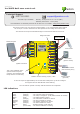
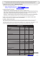
Ins-30075 Net2 nano control unit
Exit button
(push to make)
Reader/keypad
Tamper switch
(optional)
Door contact switch
(held closed by door)
23/08/2012
Technical Support
Technical help is available: Monday - Friday from 07:00 - 19:00 (GMT)
Saturday from 09:00 - 13:00 (GMT)
01273 811011
support@paxton.co.uk
12V DC
power supply
This is the heartbeat of the
system and should pulse
regularly. This indicates that
the processor is functioning.
Net2Air wireless activity (Tx/Rx) - Blue
12V (Green) - Power LED
Lock (Orange) - The 12V lock output is energised
Relay (Orange) - The relay is energised - (N.O./COM contacts are closed)
Alarm (Red) - 12V Alarm output is active
Exit (Orange) - The exit button contacts are closed
Contact (Orange) - The door contacts are closed
Tamper (Orange) - The tamper contacts are closed
PSU (Orange) - The PSU contacts are closed
Net2Air (Blue) - Net2Air interface Tx/Rx activity
OK (Green ash) - The internal software is running
LED indications
Documentation on all Paxton products can be found on our website - http://www.paxton.co.uk/
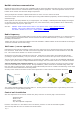
This access control unit uses wireless communication. It is recommended that a Net2Air
site surveyor is used to determine the best position for the bridge and control units.
Diagnostic LED's
This wireless unit requires a Net2Air bridge to communicate with the server PC.
*
Not connected
*
Lock release
A new unit requires approximately 30 seconds after initial power up to self congure.
During this time the OK LED will not be ashing.
The unit will not operate correctly until this function has completed.
Paxton