
Instruction Manual

BC 402 Compact Card Reader
Installation
Doc. No. 016/1
Page 2
BC 402 Compact Card Reader
Configuration
Doc. No. 016/1
Page 3
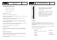
Bewator P.S.U.
173-104
Exit Request
(Push to make)
Grey Pair
White Pair
Electric
Lock
Black Pair
Setting up the system.
There are three types of card required to operate the BC 402, they consist of the following;
Control Cards (Plastic)
1) The Master card - This card is used to initialize the unit and set the door release time.
2) Fail Open/Fail Locked Card - This card is used to change the logic of the door output. This card
is linked to the Master Card, so may only
be used after initialisation, and only on the reader(s)
initialised with the associated Master Card.
Shadow Cards (Paper)
These are used to issue and delete the User Cards. One shadow card is used for each User card. The
Shadow Cards are also linked to the Master Card
User Cards
The cards that will be used day-to-day by the personnel, these may be standard Bewator IB-1 cards or
even the user's bank or credit card.
Initial Operation
When the BC 402 is first powered up the Green arrow L.E.D will flash, which indicates that the reader
requires initialisation.
At this stage (and this stage only) the BC 402 requires to be initialised with the Master card.
Carefully swipe the Master card once in the reader in a downwards direction.
The arrow L.E.D will go continuously green and the unit will give a confirmation bleep. If the L.E.D
continues to flash, the card has been mis-read.
Setting the Door Output Logic
The reader must now be set according to the type of electric release to be used. This may be either
"Fail Locked" (power to release) or "Fail Open" (power to lock).
After initialisation, the unit is set to "Fail Locked" operation. If "Fail Open" operation is required,
swipe the Fail Open/Fail Locked Card once
. This will toggle the operation of the output. Swiping the
card again will return the reader to "Fail Locked" operation
Once this initialisation has been completed the BC 402 is ready for use
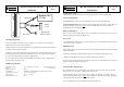
Mounting Instructions
The unit is mounted to the wall by means of 2 fixing screws, and these are then locked by
means of the small screw in the base of the unit.
Insert the 2 fixing screws into the wall at the correct spacing for the 2 holes in the back-plate of
the reader, using the template provided.
Tighten the screws down until the head is 2mm from the wall. Slacken off the locking screw in
the bottom end of the reader until the mounting hole is clear. The reader may then be put on
over the screws, and pushed down slightly to engage the slot.
Once the reader is firmly located, the small locking screw in the base may be tightened up to
lock the reader to the fixing screws
Technical Specification
Operating Voltage 12 to 16 Volts A.C. or D.C. (Bewator TABC Power
Supply No. 173-104)
Quiescent Current 80 mA
Lock Output MOSFET 750 mA maximum at supply voltage ( DC )
Operating Temperature -20 to +60 Centigrade
Measurement 89 * 34 * 34 mm
Environmental rating IP *7