
User's Manual

PAGE 2
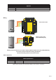
Cable extensions
Red 12v dc
Brown
Orange
Green
Yellow
Blue
Mauve
Black/White
Brown
Yellow
Reader 1
Orange
Keypad 1
+12v
0v
N.C.
N.O.
Com
N.C.
N.O.
Com
Alarm Output
0v
Contact
0v
Exit
0v
Tamper
PSU
Rx
Tx
Relay 1
Relay 2
Exit
Contact
Tamper
PSU
OK
5v
12v
Red
Brown
Orange
Green
Yellow
Blue
Mauve
Black/White
Brown
Yellow
Orange
Reader 2
Keypad 2
Power
Relay 1Relay 2Inputs
Network
CAT5 cable coding
White/Green
Green
White/Orange
Orange
1
2
3
4
Screen or spare cores
from network cable
CAUTION: for 12v d.c. readers only. For
correct connection of old 5v readers, refer to
instructions.
Serial number
241821
Test ID: 012345678901
z-1440
3 24898 00000 4
xR
Green
White/Green
1
Screen or spare cores from
network cable
White/Orange
3
Orange
4
K
1
r
e
d
ae
R d
a
py
e 1
12V
Alarm Output
R le ay 2
N.C.
N.O.
Com
N.C.
N.O.
Com
0 V
0V
Exit
0 V
PSU
0V
Contact
Tamper
R le ay 1
V
2
1
V
5
KO
T
e
p
m
a
r
tca
tn
o
C
t
i
xE
R l
e
a
y 1
x
T
U
S
P
Keypad 2 Reader 2
s
t
up
nI P ewo r
R le
a
y
2
C
A
n
i
doc
e
l
b
ac
5
T g
k
r
o
w
t
eN
+V out
R
ed LED
Amber LED
Green LED
Data/D0
Clock/D1
Media Detect
0V out
Data
Load
Clock
t
u
o
V+
D
E
L
d
e
R
D
E
L
r
e
b
m
A
D
E
L
n
e
e
r
G
0
D
/
a
t
a
D
1
D/k
c
o
l
C
t
c
e
t
e
D
a
i
d
e
M
t
u
o
V
0
a
t
a
D
d
a
o
L
k
c
o
l
C
Net2
2
Wiring
Wiring methods shall be in accordance with the National Electrical Code (ANSI/NFPA70),
local codes, and the authorities having jurisdiction.
Use Max length Type
Reader 100 yds 10 core, shielded - Beldon 9540, Alpha 1298C (22AWG) or equivalent
Cable Specication
NOTE: Where selected, any equivalent cabling / wire must be ‘ UL Listed ‘
Part number Description
353-110-US Mullion PROXIMITY reader
Options
All interconnecting devices must be UL Listed.
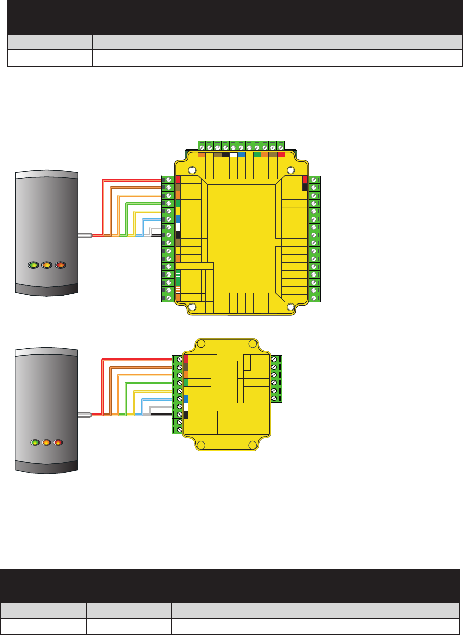
Net2 control unit
Red 12V
Brown
Orange
Green
Yellow
Blue
Mauve
Exit
Contact
Black
Card
re
a
d
e
r
o
r
k
e
y
p
a
d
12v
0v
N.C.
N.O.
Com
Bell
PowerDoor relay
Alarm
witch
2
S
Control
unit
In
p
u
t
s
CAUTION: For 12V d.c. readers
only. For corr ect connection of old
readers, refer to instructions .
C
a
r
d
r
e
a
d
e
r
o
r
k
e
y
p
a
d
I
n
p
u
t
s
D
o
o
r
r
e
l
a
y
Po
w
e
r
A
l
a
r
m
B
e
l
l
1
2
V
0
V
N
.
C
.
N
.
O.
C
O
M
CA
U
T
I
O
N
:
Fo
r
1
2
V
d
.
c
.
r
e
a
d
e
r
s
o
n
l
y.
Fo
r
c
o
r
r
e
c
t
c
o
n
n
e
c
t
i
o
n
o
f
o
l
d
r
e
a
d
e
r
s
,
r
e
f
e
r
t
o
i
n
s
t
r
u
c
t
i
o
n
s
.
C
o
n
t
a
c
t
E
x
i
t
Switch2
12V
Red LED
Amber LED
Green LED
Data/D0
Clock/D1
Media Detect
0V
Switch2 control unit
(not evaluated by UL)