Paxton ins-40213-US Paxlock US
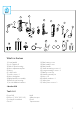
? 5 3 9 10 2* 12 11 4 14 8 6 13 1 7 16 19* 17 15 x2 20 18 21 22 X3 x2 What’s in the box 1) Front handle 2) Lock Cylinder * 3) Paxlock front housing 4) Motor adjustment plate 5) Motor 6) 2-3/8” Latch 7) Latch screws x 2 8) Motor backplate 9) Backplate/Rose assembly 10) Paxlock rear housing 11) 4 x AA Alkaline batteries 12) Rear battery cover 13) Rear handle cover 14) Rear Handle 15) Small mounting screws x 2 16) Long mounting screws x 3 17) Battery cover key 18) Handle removal pin 19) Ke
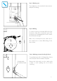
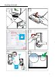
Step 1: Marking out 1 Tape template to door, mark holes then remove template for drilling. 2-3/8” (60mm) backset Step 2: Drilling 2 To ensure accuracy you should drill holes from both sides of the door towards the center. This avoids the risk of damaging the door face when the drill breaks through. Make sure to include pilot holes either side of the central hole to ensure flush fitting of the motor plates.
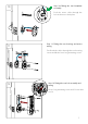
Step 4: Fitting the door latch Attach the latch using the screws provided. 5 Step 5: Fitting the strike plate Close the door to mark the horizontal line of the strike plate. Measure one half of door thickness from door stop to mark vertical center line of the strike. Drill 1” (25.4mm) hole, 1/2” (12.7mm) deep at intersection of horizontal and vertical center lines. Cut out jamb 3/32” (2.4mm) deep or until the strike is flush with jamb. Tighten the strike plate screws securely.
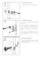
Step 7: Rotating the motor adjustment plate 7 - 2” (50mm) To ensure that the motor adjustment plate is at the correct distance, rotate until it sits flush with the door and the motor has engaged properly. Please refer to the diagram for the correct position of the plate for each door thickness. - 1-3/4” (45mm) 8 Step 8: Ensuring the latch engages Make sure the tail of the latch is engaging with the motor retractor correctly as illustrated.
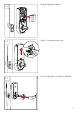
10 Step 10: Fitting the rear backplate assembly Feed the motor cable through the hole in the motor back plate. 11 Step 11: Fitting the rear housing and motor wiring Feed both the cables through the rear housing cutout and fit the lower long mounting screws. 12 Step 12: Fitting the rear lock assembly and wiring Fit top, long mounting screws and 2 lower short screws.
13 14 15 Step 10: Fitting the batteries Step 11: Securing the rear cover Step 12: Fitting the cover plate and handle 6
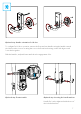
Optional step: Handle orientation for LH door To configure for LH door operation, remove the front and rear handles using the handle removal pin. Unscrew the 4 screws securing the rose to the front/rear housings, rotate 180 degrees and screw back together. Refit the handles, and push home until the axle engagement clicks. Optional step: Contact switch Optional step: Inserting the handle washers Handle feel can be tightened with the use of the included washers.
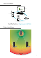
Software installation x1 ≤ 200 x1 ≤ 1000 Net2 Pro/Net2 Lite: http://paxton.
Enrolling a PaxLock 1 2 3 4 5 6 9
PaxLock reset 1 2 3 4 Battery replacement 1 2 3 4 10
Specifications Features Min Typ Max 10,000 Maximum number of users/tokens Access Levels 250 Time zones 64 Door unlock time 1 sec 60 secs Recommended number of Paxlock’s per Net2Air bridge 10 Net2Air bridge per system 200 50 ft Net2Air wireless range 3,584 Events stored Environment 4 x AA Alkaline Battery type Typical Battery life Operating temperature Max Min 20,000 operations 30,000 operations 0 °C (-32 °F) +55 °C (+131°F) Moisture resistance IPX4 External Use No Vandal resista
+44 (0)1273 811011 support@paxton.co.uk paxton.support +44 (0)1273 811011 support@paxton.co.uk paxton.support +1(800) 672-7298 supportUS@paxton-access.com usapaxton.support +1(800) 672-7298 supportUS@paxton-access.com usapaxton.support +49 (0) 251 2080 6900 support@paxton-gmbh.de paxton.gmbh.support +31 (0)76 3333 999 support@paxton-benelux.com paxton.benelux.support +31 (0)76 3333 999 support@paxton-benelux.com paxton.benelux.support +31 (0)76 3333 999 support@paxton-benelux.com paxton.benelux.
The declaration of conformity is available on request. Contact details are provided at: http://paxton.info/596 These products are not suitable for retail sale. All warranties are invalid if these products are not installed by a competent person. North America:Product Compliance and limitations Wiring methods shall be in accordance with the National Electrical Code (ANSI/NFPA70), local codes, and the authorities having jurisdiction.
14
Made in the UK © Paxton Ltd 1.0.